W4NFR AMPLIFIER PROJECT
Pair of 3-500Z Tubes
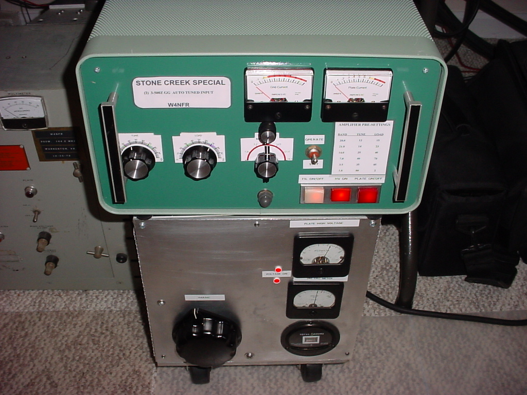
"Stone Creek Special"
Finished Amplifier and Power Supply
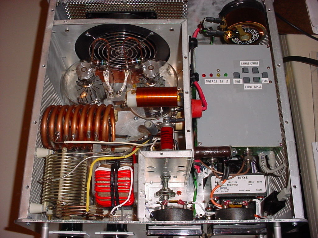
Top View
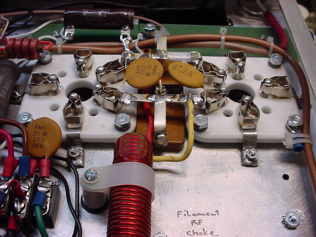
Bottom View Showing Tube Sockets and Filament Choke
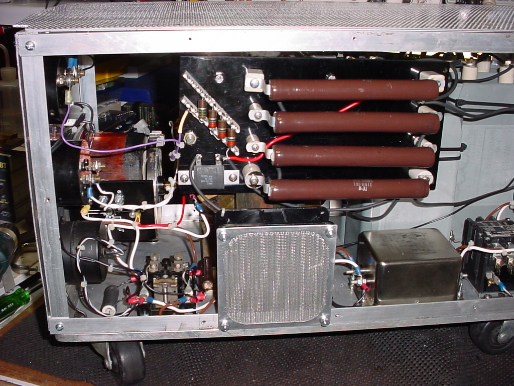
Side View of HV Power Supply
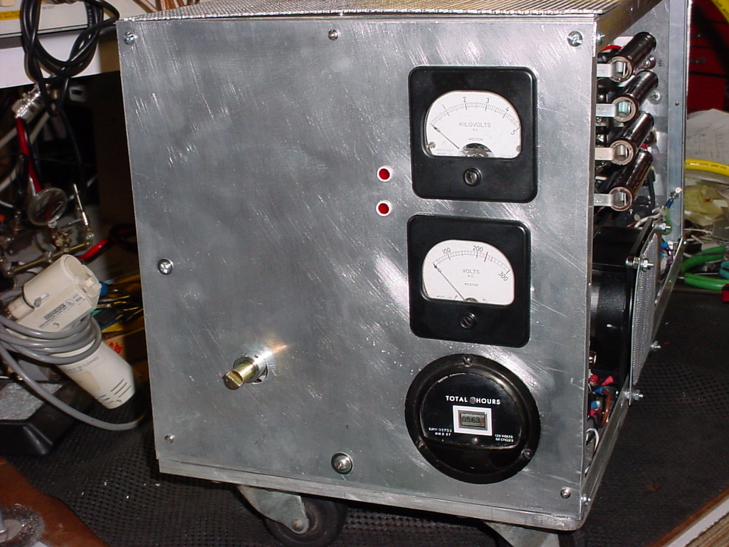
Front View of HV Power Supply
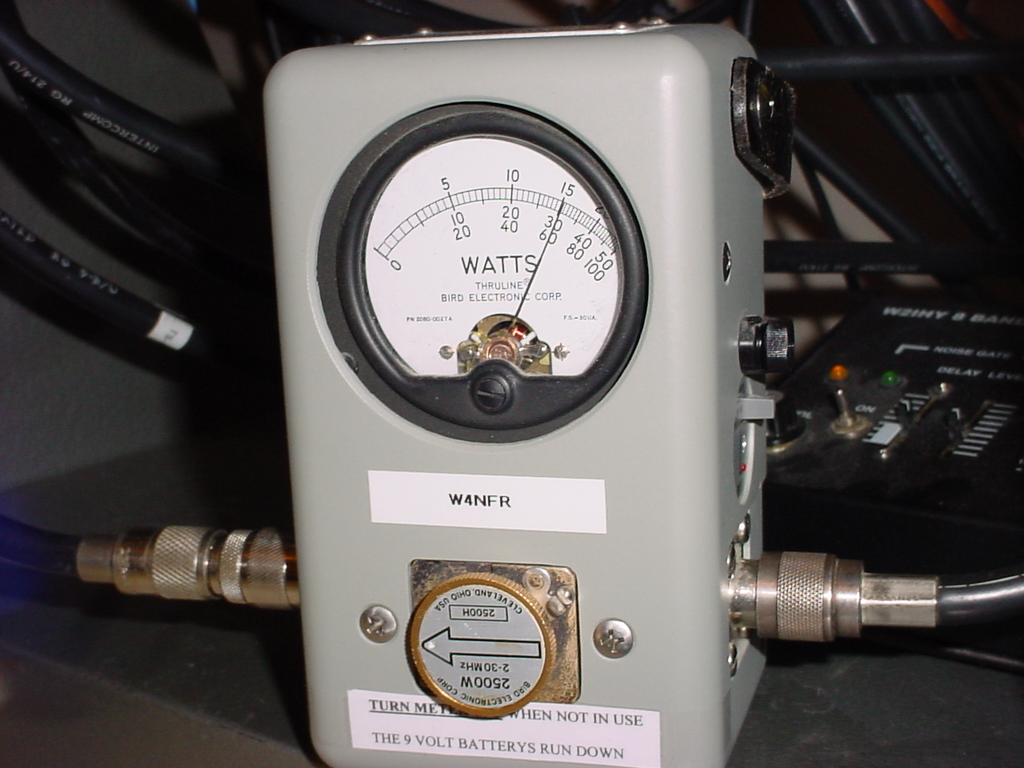
Power Output
See the write up after the Schematics and Photos:
AMPLIFIER RF DECK
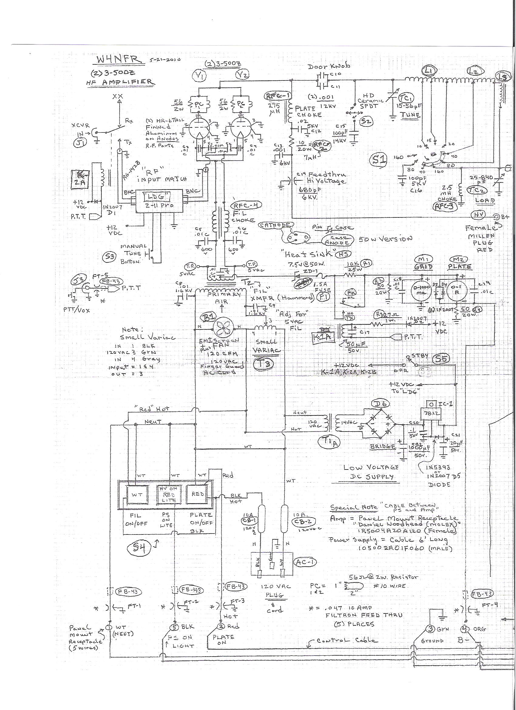
AMPLIFIER RF DECK
HIGH VOLTAGE POWER SUPPLY
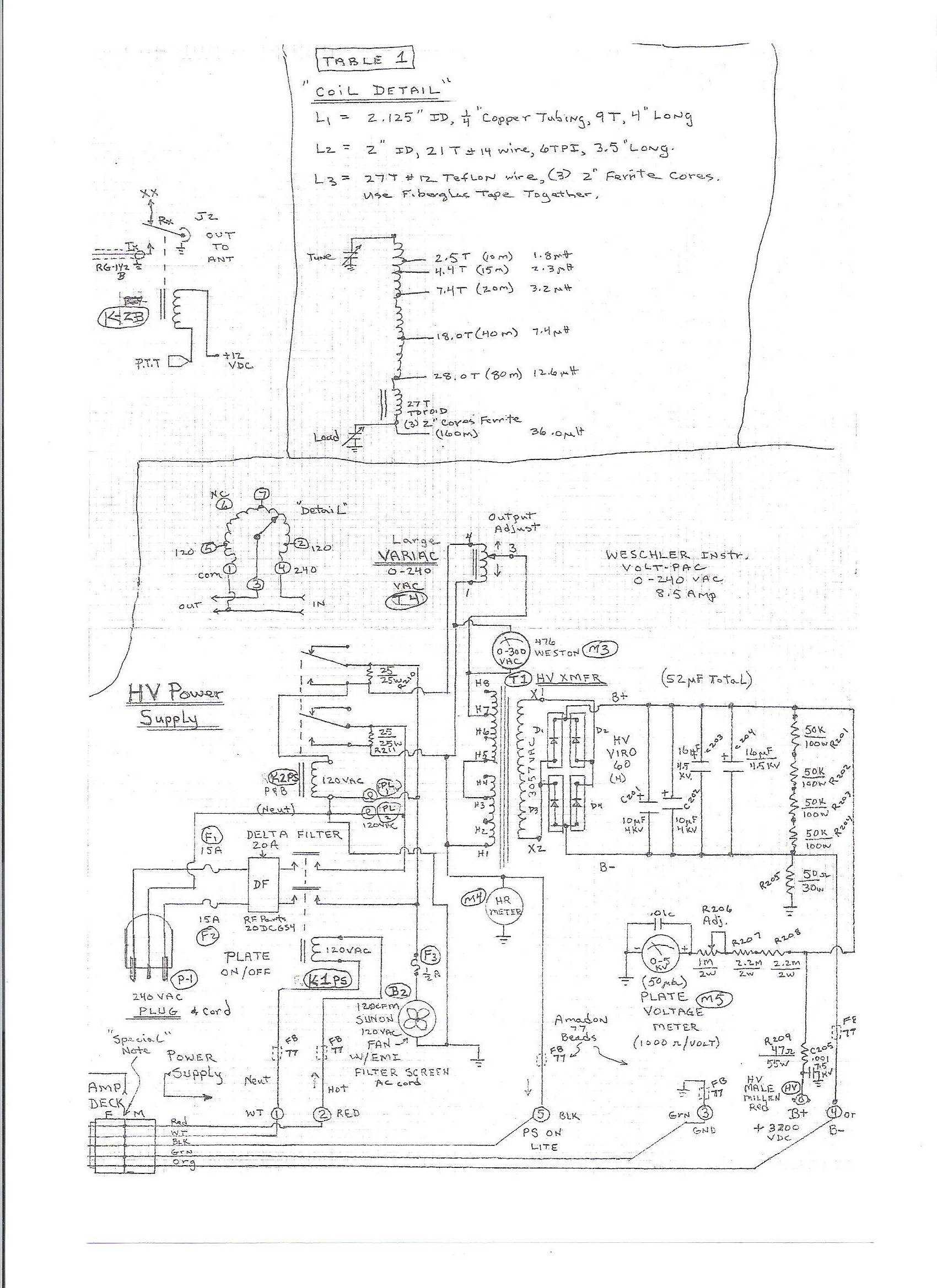
HIGH VOLTAGE POWER SUPPLY
WRITE UP & DESCRIPTION
STONE CREEK SPECIAL
(2) 3-500Z HF AMPLIFIER
By
William G. Moneysmith, W4NFR ; w4nfr@earthlink.net
The following describes a 160-10 meter linear amplifier that uses a
pair of 3-500Z triode
power tubes. It was designed and constructed by William Moneysmith,
W4NFR. The
amplifier features fast warm up and 1500-Watt RF output with 100-Watts
of drive.
The 3-500Z is a relatively inexpensive tube and has been around for a
long time. Each
tube has an anode dissipation of 500 watts, 20-Watt grid dissipation
and plate voltage up
to 4000 volt. Each tube has a 5 Volt/20 Amp filament
requirement. With plate
dissipation of 1000 Watts they are not as rugged as some more expensive
tubes.
However, in SSB service, they are rugged dependable workhorses and much
less
expensive to replace this day and age. The amplifier can be easily
duplicated and
provides full output. There have been many amplifiers built around the
popular lineup of
a pair of 3-500Z tubes. This amplifier incorporates improvements
and has a different
look. A matching 3200 VDC adjustable HD power supply is included.
The amplifier uses a conventional grounded grid design. The input
tuning uses a
commercial computer-controlled input tuner, model LDG-Z11Pro, from LDG
Electronics. (www.ldgelectronics.com) and really simplifies the
design and eliminates
the need to manually tune the input.
Page 2
STONE CREEK SPECIAL
(2) 3-500Z HF AMPLIFIER
By
William G. Moneysmith, W4NFR ; w4nfr@earthlink.net
The output is a pi-network using two air wound coils for 10 through 80
meters and a
toroid coil for 160-meter operation. The tune and load capacitors
are air variables. There
is a heavy-duty auxiliary ceramic switch (S2) to add 100 pF of fixed
capacitance for 160
and 80 when needed.
Cooling is accomplished using a 4” muffin fan, which provides 120 CFM
around the
tubes. The ambient noise is minimal.
Chassis and cabinet can be made or purchased. My amplifier has a
small physical
appearance, using a gutted out Heathkit SB-220 chassis and cabinet
obtained from Ebay.
The cabinet is well ventilated and rugged. Using the old chassis
saved many hours of
metal work. The amplifier package is very compact, but did yield
some challenges
during construction. A new front panel was made from an old
aluminum rack panel and
custom fitted to the old Heathkit chassis.
The RF deck required a new front panel to accommodate the mounting of
the tune, load
capacitors, auxiliary switch, meters, and band switch layouts.
Fortunately, the original
chassis provided shielding for the meters. A Greenlee chassis punch was
used for cutting
the meter holes.
Page 3
STONE CREEK SPECIAL
(2) 3-500Z HF AMPLIFIER
By
William G. Moneysmith, W4NFR ; w4nfr@earthlink.net
The amplifier project was constructed in my garage using basic
tools. The tools include
a band saw, jig saw, drill press and common hand tools. One can
build your own cabinet
and chassis, but I purchased the old Heathkit cabinet and chassis on
Ebay for a very
reasonable price. New commercial cabinets are expensive, so I
would recommend
buying used at a Hamfest to save money. A fresh coat of paint
will do wonders for an old
cabinet!
It is wise to collect all the parts needed before construction.
This will help you determine
how to layout the amplifier. I started the project by mounting
the tube sockets; filament
choke and transformer, barrier strips, switches, meters, relays,
cooling fan, control cable
chassis connector, and HV flanged connector.
Once the components are in place you can start wiring the amplifier. On
the amplifier
deck is a 12 Volt DC regulated power supply to provide power to the LDG
input tuner
and the two 12 VDC relays for PTT operation.
The meters have custom scales made using a great piece of software
called METER,
available by downloading from James Tonne, at
(www.tonnesoftware.com). The amplifier
deck uses two 1 ma meters. I made one scale for the grid and one
for the plate current.
The scales were printed on inkjet printer using photo paper. You can
add your call sign
and customize the scales and colors. Also, used this program to
make the tune, load and
band switch labels.
Page 4
STONE CREEK SPECIAL
(2) 3-500Z HF AMPLIFIER
By
William G. Moneysmith, W4NFR ; w4nfr@earthlink.net
The tube filaments are powered by the T2 Transformer, which provides 5
VDC @ 30
Amp. of current to the RFC-4. When S4, the Filament on/off
switch, is activated, the B1
Fan, the T2 Filament XMFR and the Low Voltage 12 VDC power supply is
activated.
The filament voltage is adjustable using a small VARIAC TRANSFORMER
(T3). Using
a very accurate meter, measure the XMFR (T2) T.P. for 5 VAC. A 5
VAC filament will
last a long time.
The 12 VDC PS powers the input/output and bias relays. The RF in
and out relay is
energized first and then the bias relay is energized last. The
10K (R1) biases the tubes to
cut off in standby receive mode. A 7.5 @ 50 Watt Zener diode is mounted
on a heatsink
and used for bias and limits the idle current.
I used the LDG-ProII to automatically tune the input to the pair of
3-500Z tubes. I
bought and removed the original cabinet. Then I constructed my
own custom box made
from G-10 PC board, to provide a shielded compartment for the tuner and
move the
operating controls to the top. BNC female chassis connectors were
added for easy
connection of the in and out cables. A connector for the 12 VDC
was added and a pair of
wires brought out for remote manual start from the amplifier front
panel. With the
thousands of memories, I never have to retune. The tuner works great
and simplifies the
input-network design, construction and operation.
Page 5
STONE CREEK SPECIAL
(2) 3-500Z HF AMPLIFIER
By
William G. Moneysmith, W4NFR ; w4nfr@earthlink.net
SPECIAL DETAILS
RFC-1 Plate Choke is a ferrite loaded RF Plate choke using a value of
275 uh and used
To eliminate any resonance in the Ham bands. This lessons the chance of
parasitic
oscillation. The ferrite RF choke is wound on Teflon or Delrin
with ferrite embedded
inside the Teflon making a very compact choke.
The control cable between the amplifier and the power supply is
accomplished using
“Daniel Woodhead” MOLEX cable and panel mount receptacle. A
female panel mount
receptacle, (Part # 1R5004A20A120), is mounted on the rear of the
amplifier deck. A 6
ft. cable with matching male connector, (Part # 105002A01F060 male 6’),
run from the
high voltage power supply and connects to the amplifier deck. This is
very high quality
cable and panel mount. Lesser quality can be used and not critical, but
good quality 16
AWG wire and connectors is recommended for dependability.
AMPLIFIER CIRCUITRY
The two 3-500Z tubes are connected in parallel. Each of the three grid
pins of the tube
sockets is grounded to the chassis. The drive signal goes to the
filament circuit of the
tubes, which is isolated from ground by a bifilar RF choke
(RFC-4). Mica capacitors
(C1, C2) are used to distribute the driving signal to the filaments of
the tubes.
Page 6
STONE CREEK SPECIAL
(2) 3-500Z HF AMPLIFIER
By
William G. Moneysmith, W4NFR ; w4nfr@earthlink.net
In the plate circuit, plate high voltage is applied to the tubes
through a heavy-duty RF
ferrite loaded choke (RFC-1) and resistor (RFC-2). Two 1000 pF @ 12 kV
ceramic
doorknob capacitors is used for the high voltage plate blocking
capacitor. The PC-1
and PC-2 are made using two 5” # 10 copper wires, bent in a U
shape. They
are 2” x 1” x 2” and a 56 ohm, 2 Watt resistor is soldered
across the input of the U
shaped wire.
The pi-network coil is divided into three parts for highest efficiency
and ease of
assembly. The first portion covers 10, 15, 20 meters, and a
second coil is added to the
first to cover 40 and 80 meters. A third toroid coil is added to
cover 160-meter band in a
compact manner.
The band switch (S1) was obtained from Ameritron Parts
(MFJ). Use a switch with
heave duty contacts or one with dual contacts to handle the voltage and
current. For this
amplifier, I use a 6-position switch for covering 10 through 160.
It has auxiliary contacts,
so extra capacitance can be added for 80 and 160 band loading.
Tuning capacitor (TC-1) is 15-56 pF, so for 80 and 160 an auxiliary
(S2) heavy duty
switch will add 100 pF to the tune range.
Loading capacitor (TC-2) is 25-840 pF, so for 80 and 160 an additional
100 pF is added
to the range. RFC-3 is for safety and provides a path to ground if a
component fails.
Page 7
STONE CREEK SPECIAL
(2) 3-500Z HF AMPLIFIER
By
William G. Moneysmith, W4NFR ; w4nfr@earthlink.net
My desired plate load resistance is a 4700 ohms for each tube.
Ep
3200
RL= ______ =
____________ = 4700 ohm Plate Load
1.7 x
Ip
1.7 x .400
TABLE 1 shows thc coil and tap data. This is course setting data
and optimum results
can be obtained using the method described below.
Pi-Network coil taps are easy to perform. I suggest the use of an
MFJ-269 HF/VHF/UHF
SWR ANALYZER to find the best coil tap for each band. A 4700-ohm
resistor is
secured from the finned anode of each tube to ground. The MFJ-269
is connected to the
output coaxial SO-239 connector. Manually activate the in/out RF
changeover relay (K2-
A, K2-B) to the send position. Set or adjust the TC-1 and TC-2
capacitors and tune the
MFJ-269 frequency adjust to obtain the best SWR. The frequency of
best SWR indicated
is the tap resonance and you can tap and readjust until optimum tap is
achieved. This
method works great. When finished, remove the two 4700 ohm
resistors from the two
anodes.
Page 8
STONE CREEK SPECIAL
(2) 3-500Z HF AMPLIFIER
By
William G. Moneysmith, W4NFR ; w4nfr@earthlink.net
HIGH VOLTAGE POWER SUPPLY
The High Voltage power supply was built from scratch, using a 1-ft x
2-ft x 3/8”
Aluminum base. This PS is heavy when loaded with the Variac,
Transformer, Capacitors
etc., so four heavy-duty castors are mounted on the bottom for support
and mobility. All
the heavy components are mounted on the base plate.
The PS is built in a separate cabinet using the castor base and is
connected to the RF deck
using a 5-conductor control cable, with a separate high voltage (HV)
cable.
The power transformer has multiple primary taps (220/230/240 VAC) one
secondary.
The output voltage is adjustable from 0-4500 VDC using a large Variac
(T4). I use 3200
VDC to power the pair of 3-500Z-tube amplifier. A step-start
circuit is included to
protect against current surge at turn on that can damage the diode bank.
The high voltage power supply provides 3200 VDC underload. It uses a
fullwave bridge
rectifier and is filtered using a total of 52 uF @4 kV oil filled
capacitors. Whenever the
HV supply is plugged into the 240-volt line, it will not operate until
activated by the RF
deck. 120 VAC originating from the S4 Plate on/off switch will
turn on the K-1PS relay.
The step-start relay will then activate and the HV light on the
amplifier deck will light on
the S4 switch in about 2 seconds.
Page 9
STONE CREEK SPECIAL
(2) 3-500Z HF AMPLIFIER
By
William G. Moneysmith, W4NFR ; w4nfr@earthlink.net
HV B+ is monitored using metering. Two resistors and a pot
for calibration is used to
feed a 0-5 kV meter (0-1-mA movement). The movement is 1000/volt, so I
used two 2.2
Meg @ 2 Watt resistors, plus a 1 Meg @ 2 Watt adjustable pot in
series to feed the
meter. All the PS meters were obtained at Hamfests and are
off-the-shelf meters. These
include 0-300 VAC Primary voltage, 0-5 kV High Voltage and the Hours On
meter. The
HV cable between the RF deck and the power supply is made from a 6-ft
length of HV
insulated wire obtained from R.F. Parts. The connectors are
MILLEN HV female on
the panels of the RF deck and the PS. The HV cable uses male
MILLEN HV connectors
on the insulated wire.
AMPLIFIER TUNING
I prefer to use a device called a “Pecker” to tune all my amps
safely. These pulse devices
will get you in the ballpark without stressing the tubes.
The Pecker is used to tune your
amplifier in the SSB Mode without a CW or AM RF carrier. The Pecker is
a single
pulsed tone that works with a 70% off & 30% on duty cycle with your
transmitter in the
SSB Mode. This short duty cycle allows you to take your time on
tune-ups (or testing of
your amplifier, antenna, or other equipment), with very little chance
of tube damage,
power supply stress, and arc-over with your amplifier, or tube
transmitter, like you have
using a CW carrier. The Pecker allows you to tune your amplifier to
full Peak Output
Power quick and easy.
Page 10
STONE CREEK SPECIAL
(2) 3-500Z HF AMPLIFIER
By
William G. Moneysmith, W4NFR ; w4nfr@earthlink.net
You will never go back to the old "Peak & Dip" tune-ups with a CW
carrier for drive
once you have used a "3898 Pecker". Ask those who use a Pecker and
they'll tell you that
for speed and ease of tune-ups, you just can't beat the Pecker.
Read some of the reviews they posted at
http://www.eham.net/reviews/detail/5121 .
The 3898 Pecker uses a single pulsed tone through the radio's SSB MIC
audio circuit,
thus tuning your amplifier in SSB MODE for SSB OPERATION. You must use
a PEP
Watt meter when using the 3898 Pecker because the short duty cycle
won't let the
average reading meters show the full out-put of the amplifier. Thus
making it harder to
see when the RF hits its peak out-put. The website for Mr. Pecker
is:
http://www.3898pecker.com
The Operate/Standby switch (S5) must be switched to the Operate
position. Once you
have performed your initial tune-ups, make a “Tune” preset
chart-showing settings for
each band. This will save time in the future operation.
I would suggest not driving more than 200 ma Grid current and no more
than 700 ma
Plate current. A 100-Watt transmitter will drive this amplifier
nicely without
overdriving.
Thanks to LDG Electronics, Varian for tube data, Ebay, Molex (Daniel
Woodhead), RF
Parts, Ameritron MFJ, Henry Radio, ARRL and Mr. Pecker Electronics for
parts
information and references.
Page 11
STONE CREEK SPECIAL
(2) 3-500Z HF AMPLIFIER
By
William G. Moneysmith, W4NFR ; w4nfr@earthlink.net
TABLE 1
COIL DETAIL:
L1 = 2.125” ID. ¼” copper tubing, 9 T, 4” long.
L2 = 2” ID. 21 T # 14 wire, 6 TPI, 3.5” long.
L3 = 27 T # 12 Teflon wire, (3) 2” Ferrite Cores. Use Fiberglas tape to
wrap cores.
Tune Capacitor End:__
)
)
)---------2.5 T (10M) 1.8 uh
L1 )
)---------4.4 T (15M) 2.3 uh
)
)---------7.4 T (20M) 3.2 uh
)
--
I
)
)
)
L2 )--------18.0
T (40 M) 7.4 uh
)
)
)
)
)----------28.0 T (80M) 12.6 uh
--
I
L3
) (27 T Toroid (3) 2” Ferrite Cores)
)
Load Capacitor End__)------------------(160 M) 36.0 uh
Page 12
STONE CREEK SPECIAL
(2) 3-500Z HF AMPLIFIER
By
William G. Moneysmith, W4NFR ; w4nfr@earthlink.net
POWER SUPPLY CABINET
The Power Supply is built on a 1ft x 2ft x 3/8” Aluminum base with 4 HD
casters
mounted on the bottom. The cabinet is made by using ½”
angle Aluminum to frame in
the 1 ft x 1 ft x 2 ft cabinet. The frame is covered with
perferated Aluminum sheeting on
the two 1 ft x 2 ft sides. Solid Aluminum sheeting is used for
the 1 ft x 1 ft end and rear,
also the 1 ft x 2 ft top. A fan and EMI filter screen is
mounted on the side of the PS to
ventilate the interior.
List of Materials:
Quantity:
Description:
(1) 1 ft x 4 ft
Perferated Aluminum 0.062” thick sheet.
(1) 1 ft x 4 ft Solid
Aluminum 0.062” thick sheet.
(1) 12 ft Long Aluminum
½” Angle Stock.
(1) 1 ft x 2 ft x 3/8”
Aluminum Base.
(4) 2” Heavy Duty Casters.
Page 13
STONE CREEK SPECIAL
(2) 3-500Z HF AMPLIFIER
By
William G. Moneysmith, W4NFR ; w4nfr@earthlink.net
Amplifier Parts List:
V1, V2 = 3-500Z Triode
Vacuum Tubes, RF Parts.
C1, C2 = .01 Mica Capacitor,
Micamold. CM45B103K
J1, J2 =
SO-239 Chassis Mount.
J3
= Phono Jack, Panel Mount. (PTT) input.
C3-C7 = .01 Ceramic
Disk, 600 VDC.
C8, C9 = .01 Ceramic
Disk, 1.6 kV.
TC1
= TUNE CAPACITOR, AIR VARIABLE, 15-56 pF,
RF Parts.
TC2
= LOAD CAPACITOR, AIR VARIABLE, 25-840
pF, RF Parts.
C10, C11 = .001 mF @ 12 kV, Door Knob.
C12
= .02 @ 5 kV, HV Plastic Capacitor.
C13
= .001 @ 5 kV, Door Knob, HEC.
C14
= 680 pF @ 6 kV Feed-Through
Capacitor.
C15
= 100 pF @ 15 kVDC N750, Door Knob,
HEC HT57
C16
= 100 pF @ 5 kV, Door Knob, HEC
C17
= 50 uF @ 50 VDC.
Electrolytic Capacitor.
C18, C19 = .01, 600 VDC,
Ceramic Capacitor.
C20
= 0.1 @ 50 VDC Disc Capacitor.
C21
= 20 uF @ 50 VDC.
Electrolytic Capacitor.
Page 14
STONE CREEK SPECIAL
(2) 3-500Z HF AMPLIFIER
By
William G. Moneysmith, W4NFR ; w4nfr@earthlink.net
Amplifier Parts List:
C22
=
1000 uF @ 50 VDC, Electrolytic Capacitor.
FT-1 thru 5 = .047 uF @ 10 Amp,
Filtron Feed Thru (5 Items)
PC-1, PC2 = Parasitic
Choke, (2) 56 ohm, 2 W. Resistor (Non-Inductive).
Two pieces of 5” Long, # 10 Wire, Bent U Shape, 1” x2”
Tube Sockets = Two Ceramic, 3-500Z, Johnson Flat,
Ebay or RF Parts.
T1A
= Low Voltage Transformer, 120 VAC Pri, 14 VAC Sec @ 1 Amp.
RF Parts.
T2
= Filament Transformer, 5 VCT, 30 Amp. RF Parts, 167x5
Hammond Mfg.
T3
= Small Variac, 120 VAC. Ebay.
HR-6
= Two HR-6 Tall, Transmitting Tube Plate Cap Radiator.
RFC-1
= PLATE RF CHOKE, 275 uh, Ferrite Loaded. Ebay.
Contact: Ron Brown, Ron@rgb52.com
RFC-2
= 10 OHM, 20 WATT RESISTOR.
RFC-3
= 2.5 mh, 500 ma, multilayer choke, Miller, National, Hammond.
RFC-4
= BIFILAR 30 AMP FILAMENT CHOKE, Ebay, RF Parts.
S1
= Bandswitch, 6 position and three Aux contacts, Ameritron
(Dual HD Contacts)
Page 15
STONE CREEK SPECIAL
(2) 3-500Z HF AMPLIFIER
By
William G. Moneysmith, W4NFR ; w4nfr@earthlink.net
Amplifier Parts List:
S2
= HD CERAMIC, SPDT HV RF SWITCH. HAMFEST,
EBAY
MUST HAVE WIDE SPACING ON THE CONTACTS TO
PREVENT ARCING.
S3
= Pushbutton Switch, N.O. Momentary On.
S4
= Pushbutton Switch Assy. Consisting of
two switches and one light.
Molex Mfg. 125 VAC @ 8.5 Amp switches and 125 VAC Lamp.
S5
= SPST Toggle switch. 125 VAC @ 5 Amp.
K-1A
= Bias Switching, DPDT, 12 VDC Coil, Potter
Brumfield AMF
KT11D.
K-2A & B = RF Changeover Relay,
AMF, Potter Brumfield Div, KT11D,
12 VDC coil. Small HD, DPDT, 10 Amp Contacts. Or Equil.
D1 – D5 =
1N2007 Diode, 1000 piv, 1 amp, RF Parts or equil.
D6
= Diode Bridge or 1 amp diodes for a full wave,
MDA3500, RF Parts.
ZD-1
= Zener Diode, 7.5 Volt @ 50 Watt,
1N2805A. RF Parts.
HS
= Aluminum Heatsink, 2” x 4” x 1”
B1, B2
= Fan, 4” , 120 CFM, 120 VAC, “Sunon”, 4.7” x
4.7” x 1.5”, RF
Parts. W/AC cord and plug, finger guard and EMI filter screen.
Page 16
STONE CREEK SPECIAL
(2) 3-500Z HF AMPLIFIER
By
William G. Moneysmith, W4NFR ; w4nfr@earthlink.net
Amplifier Parts List:
IC-1
= 7812, 12 Volt Regulator, 3 terminal.
F1
= 1.5 amp Fuse and Holder.
Terminal Blocks = Three 12 terminal barrier strips or equil.
CB-1, CB-2 = 10 AMP CIRCUIT BREAKERS, 120
VAC.
AC1
= PLUG & CORD. 120 VAC, 15 AMP. USE GOOD QUALITY # 12
WIRE AND INSULATION, 6 FT LONG.
LDG TUNER = Modified LDG Model Z-11Pro Autotuner,
http://www.ldgelectronics.com
RG-142B = 4 ft long, Beldon 83242,
50 ohm Teflon.
BNC
= Two Male connectors to fit RG-142B cable.
FB-43
= 5 Ferrite Beads (FB-43).
M1, M2 = 1 Amp
Meter Movement. 2” Face.
TP
= Two Meter Test Points.
R1
= 10 k@ 25 Watt Resistor.
R2, R4
= 50 ohm @ 20 Watt.
R3
= 27 ohm @ 1 Watt.
HV Cable = Two Millen Female
Chassis Red Part # 37001D (RFParts).
Two Millen Male Plug HV Connector Red Part # 37001C
HV Wire = 20 ft
of HV-30, 60 kV Breakdown, 20 AWG, (RF PARTS).
Page 17
STONE CREEK SPECIAL
(2) 3-500Z HF AMPLIFIER
By
William G. Moneysmith, W4NFR ; w4nfr@earthlink.net
Amplifier Parts List:
Control Cable
And Panel Mount
Receptacle
= 6 ft long, “Daniel Woodhead” MOLEX Cable, 5 wires.
Part # 105002A01F060 (Male)
Panel Mount Part # 1R5004A20A120 (Female)
L1, L2, L3 = SEE TABLE 1 FOR
DETAILS.
HIGH VOLTAGE POWER SUPPLY PARTS LIST:
P-1 = 240 VAC
MALE PLUG AND 6 FT CORD, # 10 WIRE.
(2 WIRE + GROUND) NEMA.
F1, F2 = 15 AMP, 120 V FUSE.
F3 =
½ AMP, 120 V FUSE.
DF = DELTA
FILTER, RF PARTS # 20DCGS4 20 AMP EMI.
K1PS, K2PS = 120 VAC RELAY, RF PARTS # W99AX5, MAGNICRAFT, DPDT
25 AMP CONTACTS OR CONTACTOR RELAY.
PB PRD-11AYO-120.
T4
= Large VARIAC, 0-240 VAC, 8.5 AMP. (WESCHLER INSTR)
OR
Equil. Ebay.
T1
= High Voltage Transformer, 220 VAC INPUT, 3057 VAC OUTPUT
@ 1
AMP. ( HARBACH ELECTRONICS, info@harbachelectronics.com
M3 = 0-300
VAC, WESTON 476 METER.
M4 =
TIME ON HOUR METER (Hamfest).
M5 =
0-1 mA Meter, 1000 ohms/ volt, 0-5 kV. (Hamfest).
D1-4 = High
Voltage Diodes, VIRO 60, 10,000 VOLT@ 1 AMP.
Page 18
STONE CREEK SPECIAL
(2) 3-500Z HF AMPLIFIER
By
William G. Moneysmith, W4NFR ; w4nfr@earthlink.net
HIGH VOLTAGE POWER SUPPLY
PARTS LIST:
C201, C202 = 10 uF @ 4 kV, OIL FILLED HD.
C203, C204 = 16uF @ 4.5 kV, OIL FILLED HD.
R201 – R204 = FOUR 50K @100 WATT WITH MOUNTING CLIPS.
DALE, RF Parts, HL100-06Z-50K, 6.5” X 7/8”
R205
= 50 OHM @ 30 WATT, MEMCO, DALE, RF Parts.
R206
= 1 MEG @ 2 WATT POT.
R207, R208 = 2.2 MEG @2 WATT. DALE
R209
= 47 OHM @ 55 WATT, DALE, Hamfest.
FB-77
= FERRITE BEAD # 77, AMIDON or equil.
C205
= .001 @ 7.5 kV CERAMIC CAPACITOR.
R210, R211 = 25 OHM @ 25 WATT,
DALE, HLW12A1Z2S, RF Parts.
PL1, PL2 =
120 VAC, PILOT LIGHT.
WARNING ! Always use caution
when working on an Amplifier or
Power Supply.
High Voltages are present and can kill.
Use extreme caution and common sense
when using this type of equipment.
Page 19
STONE CREEK SPECIAL
(2) 3-500Z HF AMPLIFIER
By
William G. Moneysmith, W4NFR ; w4nfr@earthlink.net
BIO:
W.G. Moneysmith, W4NFR, has been enjoying HAM radio as an Extra class
licensee since 1961. Bill enjoys all facets of radio, especially
AM, CW, PSK-31, RTTY, Packet, DSSTV, QRP and chasing DX. He
is an avid electronics and Ham radio enthusiast, with a particular
interest in antennas. He has written many technical articles and
is a retired Electronics Engineer. Current activities include RV
camping/traveling, gardening, wood carving,
gold
panning, and metal detecting with my wife Lydia.
FIGURE CAPTIONS:
TABLE 1 - Pi-Network Coil Detail.
Page 20
STONE CREEK SPECIAL
(2) 3-500Z HF AMPLIFIER
By
William G. Moneysmith, W4NFR ; w4nfr@earthlink.net
REFERENCES:
RADIO HANDBOOK
22 nd Edition by William I Orr, W6SAI
Page 22.19 to 22.27
ARRL Handbook, 2006
Page 18.29 – 18.37
3CX1500D7 RF LINEAR AMPLIFIER
BY Jerry Pittenger, K8RA
Molex “Daniel Woodhead”
Catalog – Panel Mount Receptacles
Cables with Connectors
http://www.woodhead.com/eCatalog/Product
Henry Radio 2kd-5 Amplifier
11240 W. Olympic Blvd.
Los Angeles, Calif 90064
RF Parts Co.
435 S. Pacific St.
San Marcos, CA 92078
SAMS Radio Handbook
23rd Edition By William I, Orr, W6SAI
Page 17-8 to 17-14
ARRL Handbook, 1999
Page 13.1 thru 13.47
ARRL
Handbook, 1981
Pg. 23-11
Amplifier Tune-Up Safely
Mr. Pecker Electronics
http://www.3898pecker.com
The End