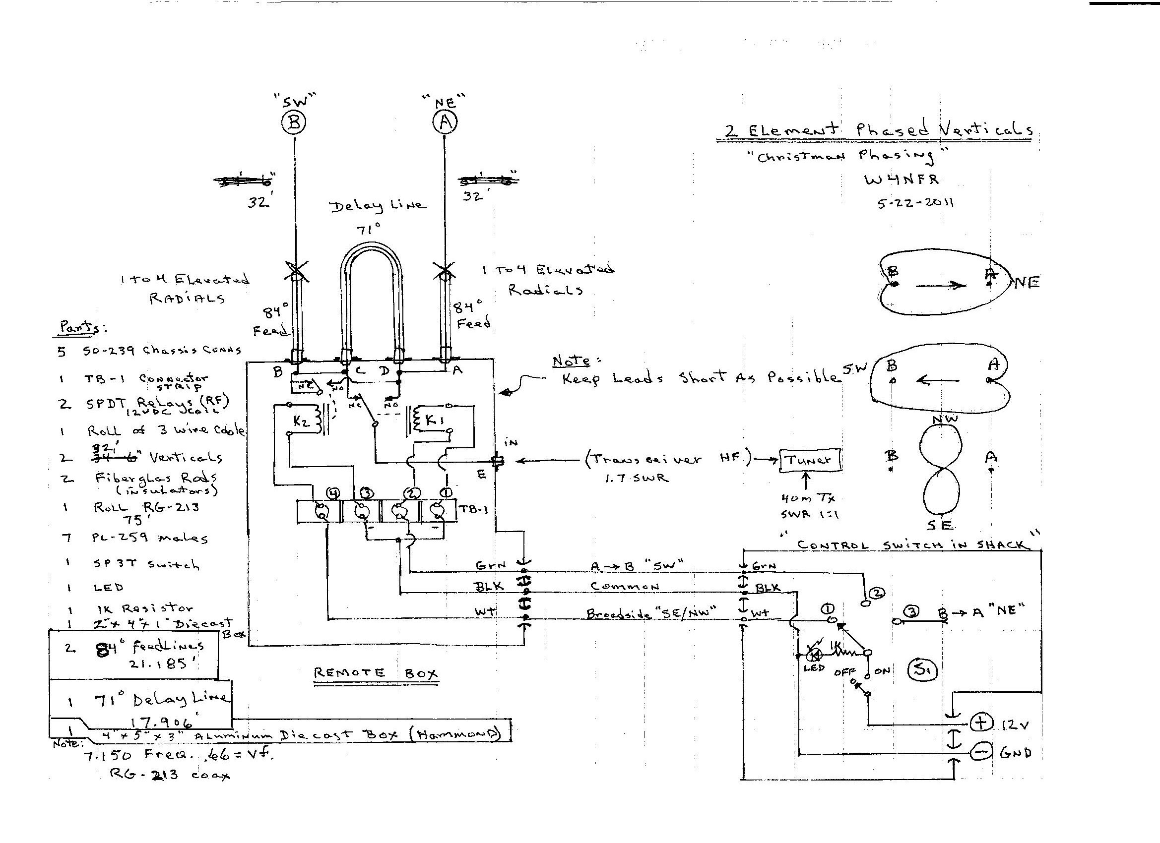
"Christman Phasing"
by
W4NFR
5-22-2011
I have always been curious about vertical antennas and how to make them efficient. Not having a lot of room for 40 meter beams, I decided to use the space I do have, which is a long wooded fence in the backyard.
I started by building a 40 Meter 1/4 wave vertical using aluminum tubing, then I made a second one to Phase with the first one. The following photos and writeup are the results.
Each antenna is installed and tuned to give a 1.1:1 SWR at the antenna connector of each Vertical. The Feed and Phasing cables are added. The finished system performs well and has very good Front to Back nulls. The SWR is a around
1.7: 1, which is a little high, but I use a Tuner to make the amplifier happy!
Note:
The Two Verticals are spaced 32 feet apart. They are elevated about 6' above ground and have two radials each. These are also elevated, so not many required. The most difficult things about antenna phasing is tuning the two antannas the same and coming up with the proper Coax lengths for the feedlines and phasing delay line. The actual length can be checked using a
MFJ-269 Antenna Analyzer Advanced II Mode.
The math to find the coax lengths is shown below.
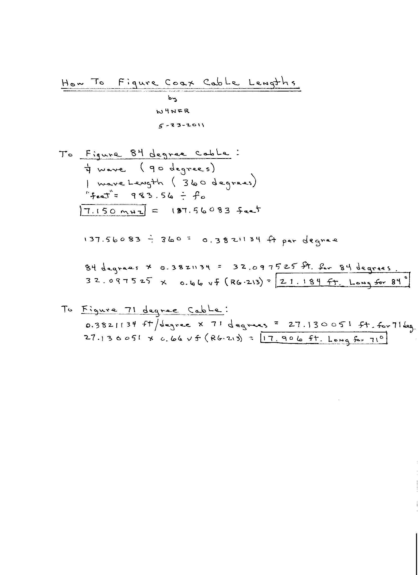
You Can Use a MFJ-259 or MFJ-269 to Measure the lengths in Degrees and verify the lengths....
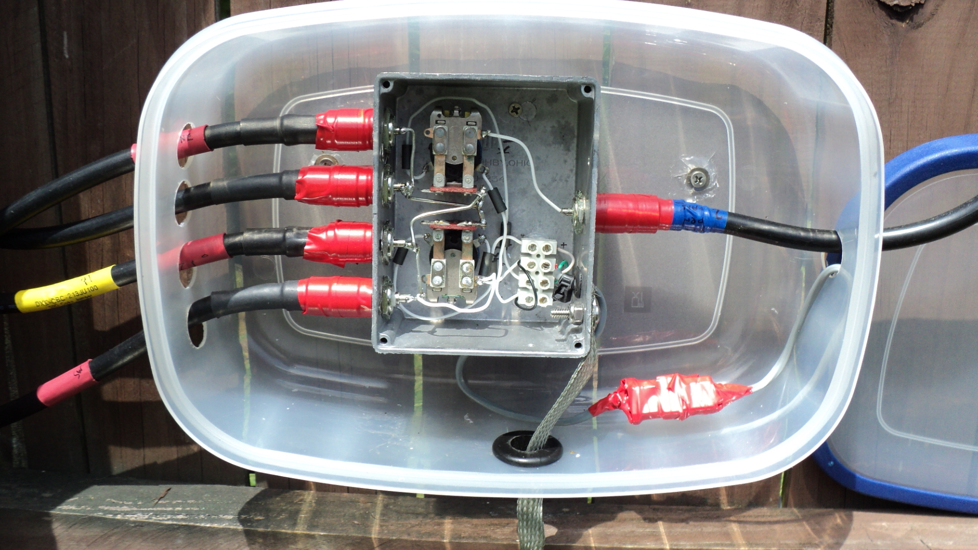
Relay Box Showing Connections
These 12 VDC Relays Are The Type That Can Handle 5KV On The Contacts
The Relays are: AMF/ Potter-Brumfield, 12 VDC, Model KT11D or equil. If these ever crap out, I will change to 12 VDC Vacuum Relays.
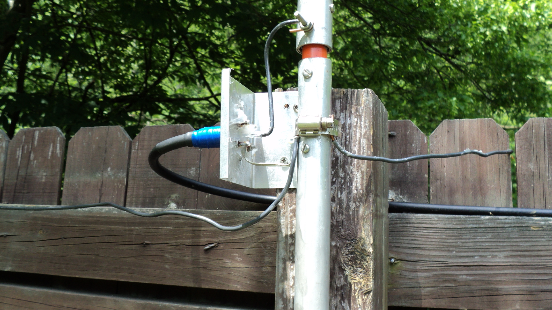
40 Meter Vertical SW and Two Elevated Radials
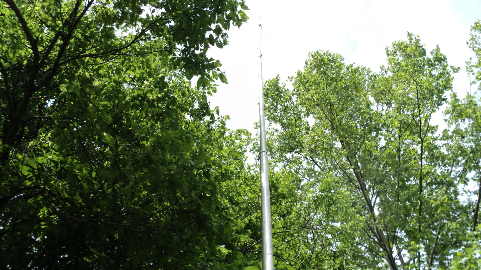
Free Standing Vertical
40 Meter Vertical NE Antenna, Fiberglass Rod is the Very Strong Insulator

Relay Box With Lid Off Showing Connections
Note: I use teflon wiring for hookups.The Ground Strap is the Safety Ground to a Rod.
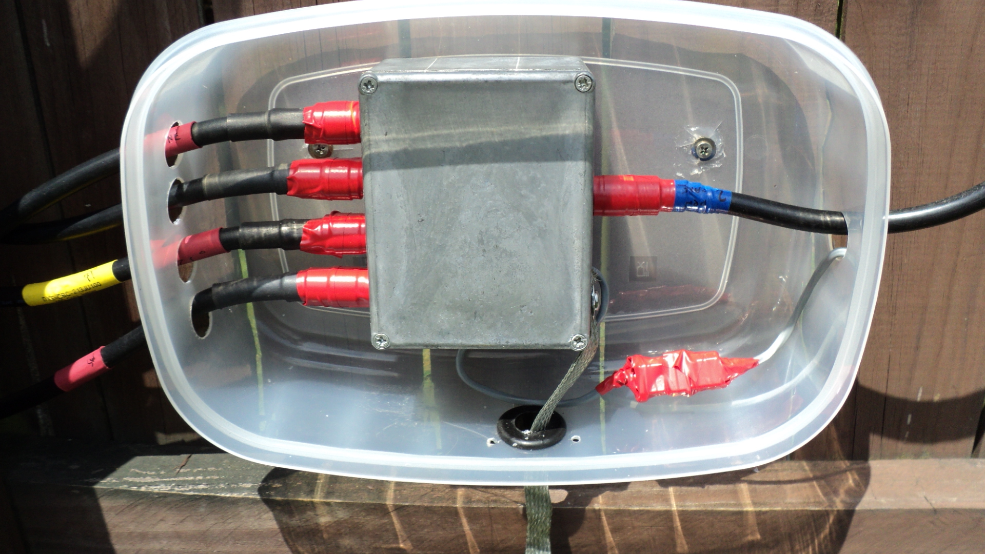
Taped Up Coax Connections, Ground Strap Goes to Ground Rod Below.
TWO small holes are drilled in the bottom as Weep Holes.
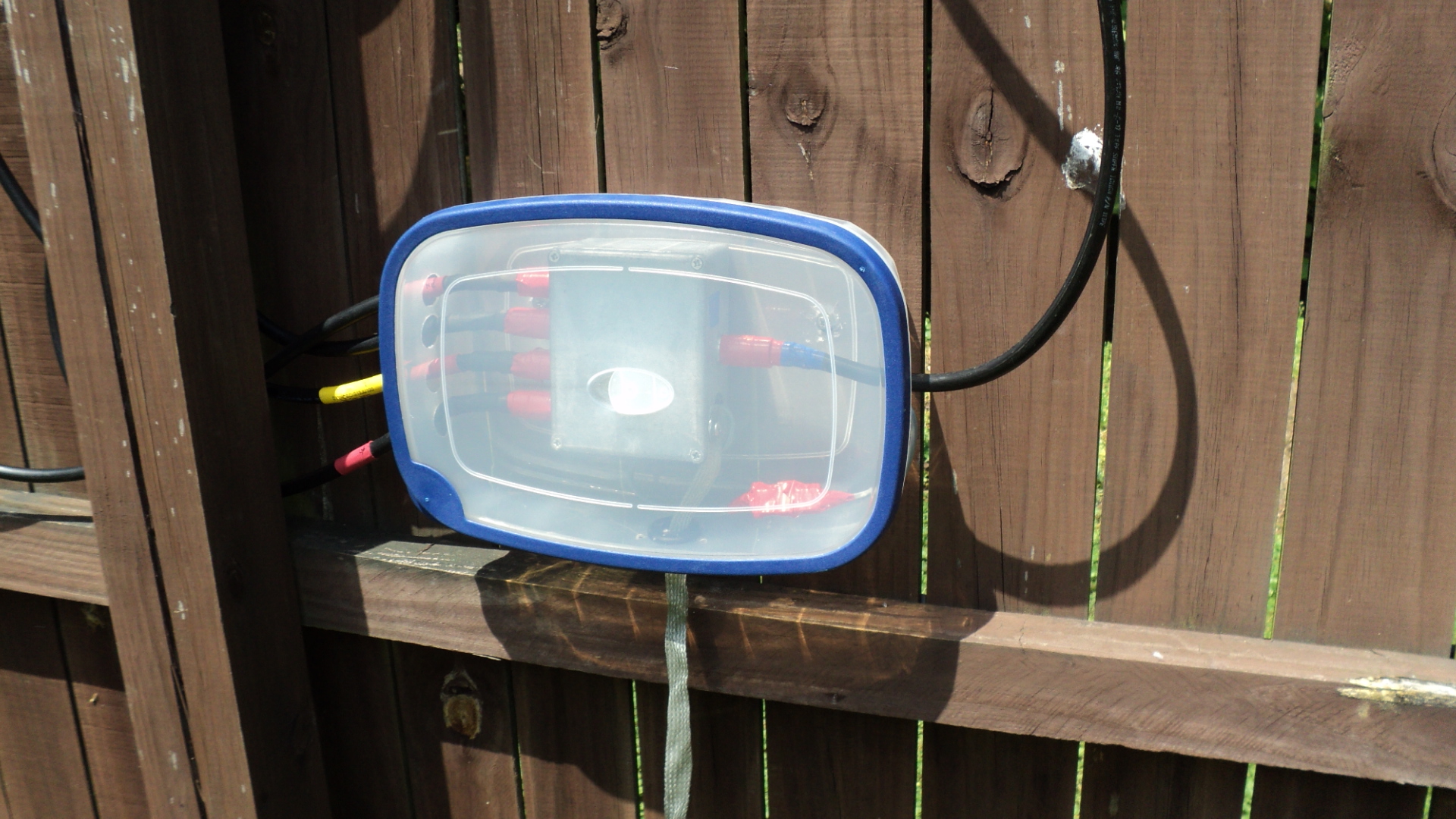
Weather RAIN Cover In Place
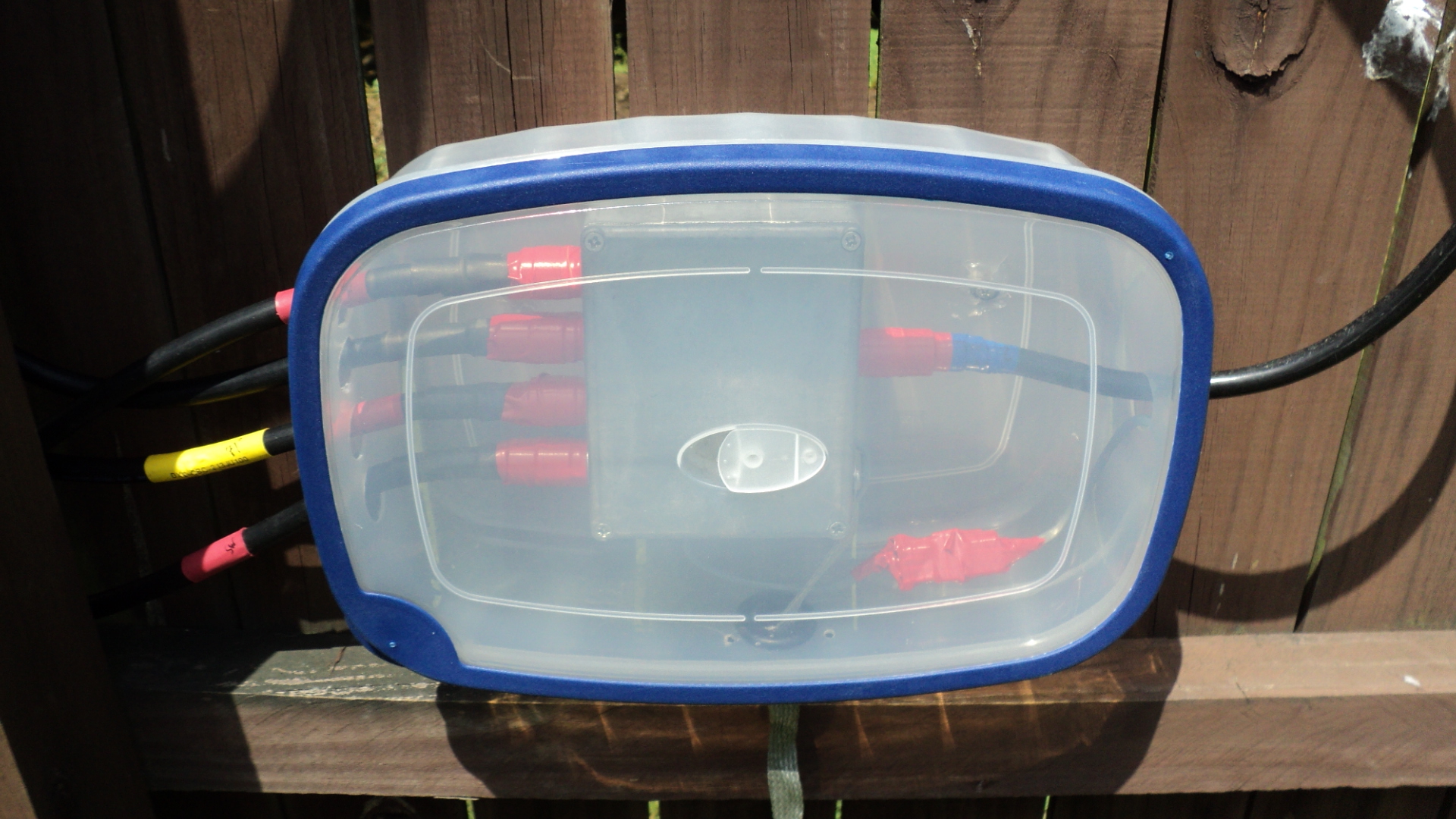
Finished Box With Lid On
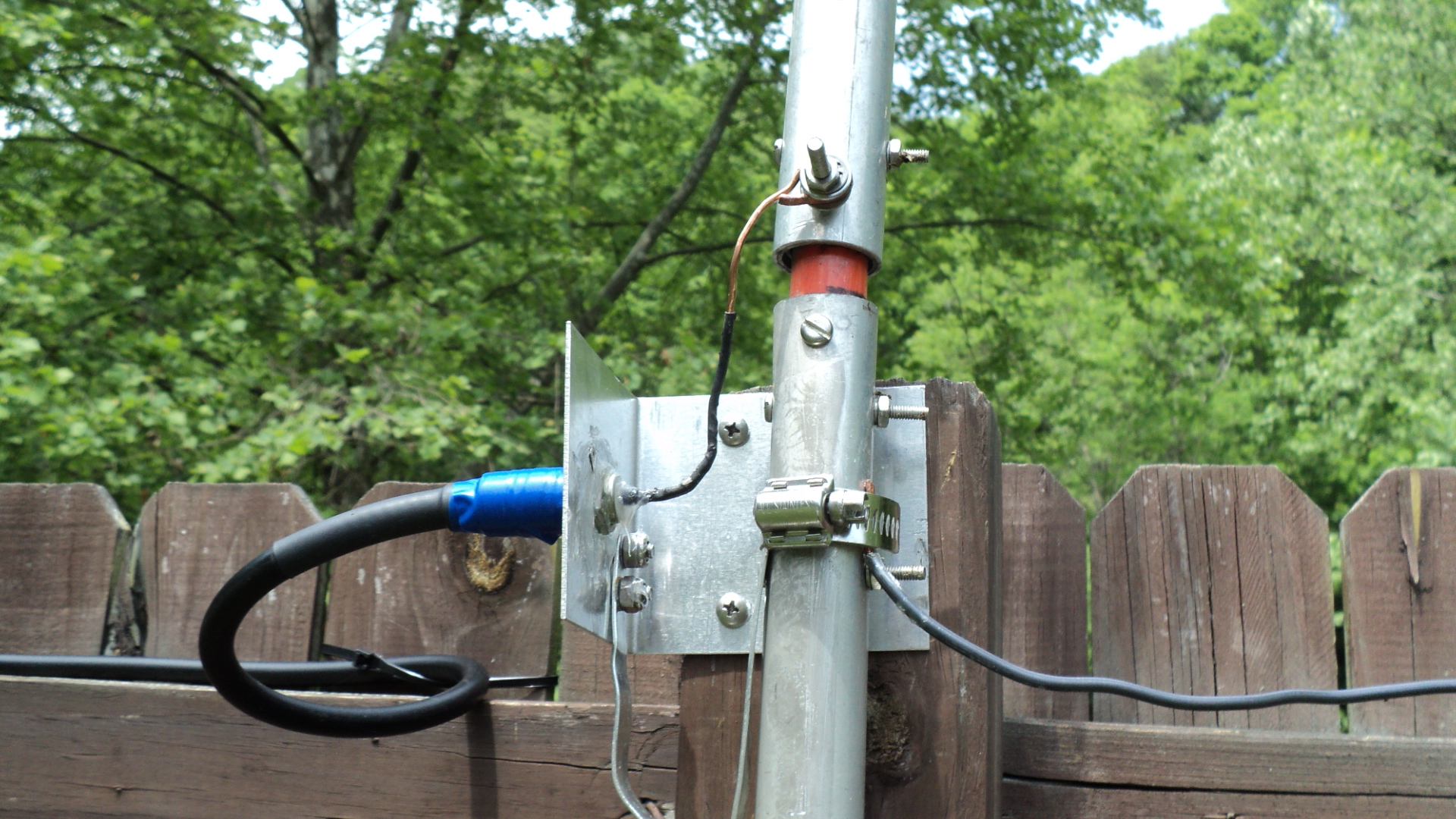
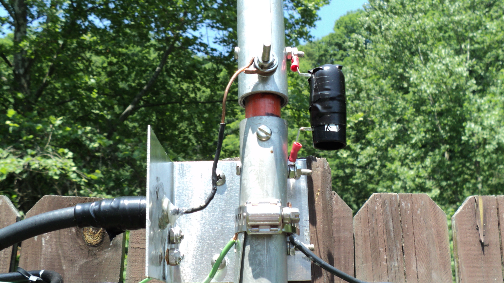
The Antennas Need A Way To Bleed Off Static Buildup. So I Added a 2.5MH choke from the Antenna Radiator to Ground.
These are available on Ebay or RF Parts.
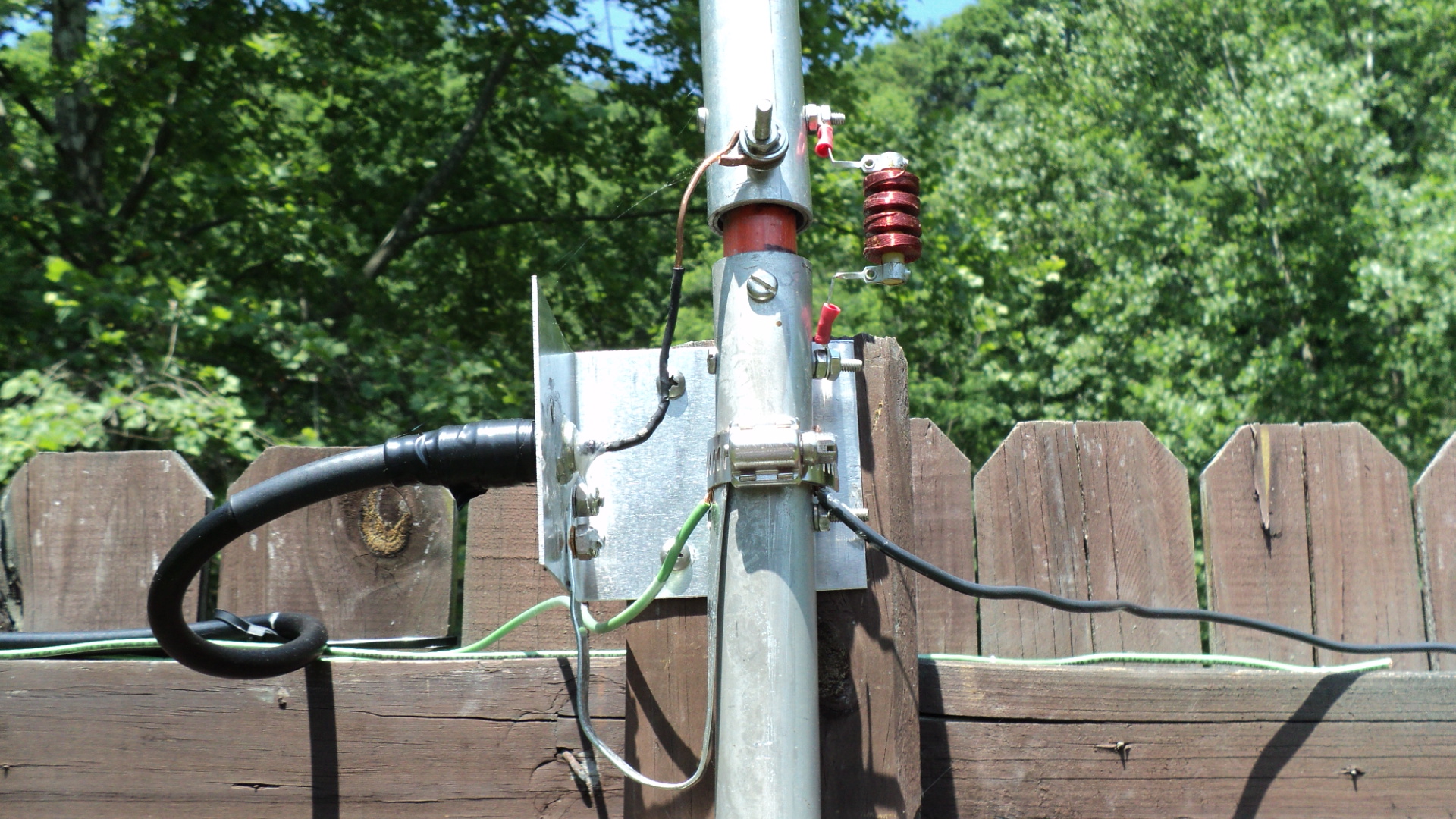
To Protect The 2.5 MH RF Choke from Rain and Ice, A Plastic Cover Was Added and Taped to secure.
A Control Box In The Shack, Switches The Three Different Antenna Pattern Configurations.
On/Off Switch on the Left, Power On LED in the Middle and the Position Switch on the Right.
This is constructed in a small HAMMOND die cast box 2" x 4" x 1" and It is Secured Under My Operating Table.
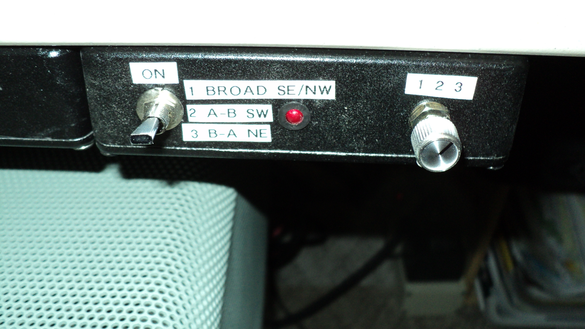
Control Box
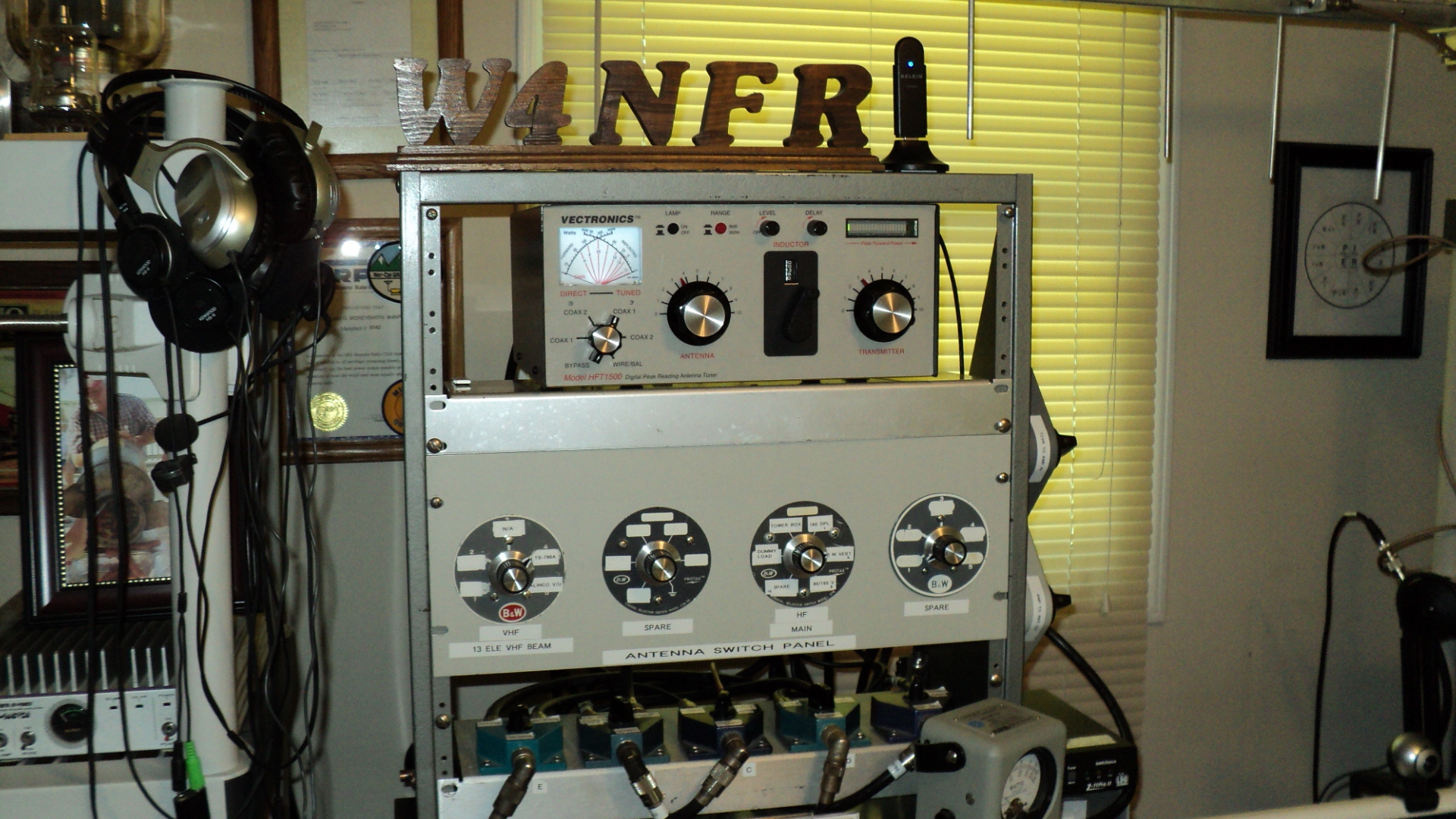
The Over All SWR is between 1.6 : 1 and 2.2 : 1, So The Coaxial Cable is routed through the Vectronics HFT-1500 Antenna Tuner to Make the Amp Happier ! It now sees 1:1 SWR.
The End !