STONE CREEK SPECIAL 600
W4NFR
8-3-11 to 8-26-11
This is a Solid State Amplifier Project. It uses 4 MRF150 MosFet Power Transistors.
The Power Supply Voltage is 50 VDC @ 21.5 Amp. The max power available is 1,075 Watts.
The Efficiency is about 65% +/- and runs Class AB Solid State.
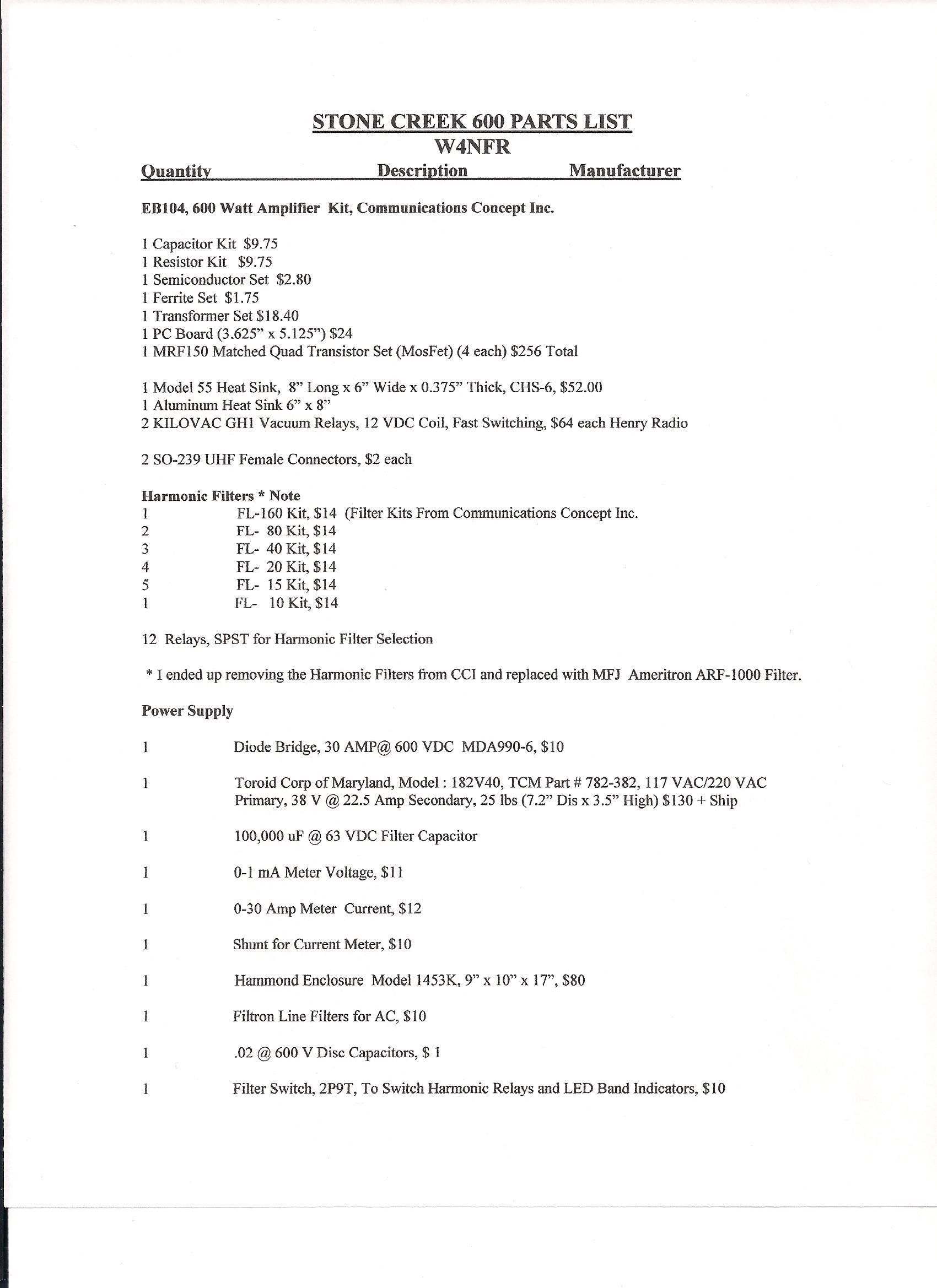
The basic amplifier is the EB-104 Parts Kit offered by Communications Concepts, Inc.
The SS Amp will handle 6 watts PEP in and provide 600 PEP out.
The Toroid Power Transformer for the 50 volt supply is sold by
Toroid Corporation of Maryland and is model 782-382.
I use a 3 dB resistive Pad on the input, so I run 12 watts out of the transceiver
and the amplifier has 6 watt input. The output is 600 + watts.
I set my bias to 5.5 volts on pin 3 of the bias regulator chip and the individual bias to 150 mA each MosFet.
This is a conservative idle CURRENT setting. The Bias is switched on with Tx and Off on Receive.
This cuts down on heat when amplifier is not in use.
Originally, the Harmonic Filters were made using parts kits from CCI.
I found that the loss was too much, so I installed a MFJ AMERITRON ARF-1000 Harmonic Filter board
and now the power out is 100 watts better.
Using the airflow from Three Low Noise 12 VDC fans cool the heat sink and harmonic filters allowing
use to 600 watts PEP.
The EB104 Bulletin by Motorola's Helge Granberg, 1983, is available and downloadable at many websites.
As a side note, it is very important to use a good grade of heat sink compond on the MosFet
devices like Arctic Silver or equiv. Good heat transfer is extremely important!
IT IS EXTREMELY IMPORTANT TO DRILL AND TAP THE 4-40 HOLES VERY ACCURATELY. USE THE CIRCUIT BOARD TO LAYOUT THE PATTERN. I USE A SCRIBE TO MARK THE COPPER HEAT SPREADER. USE CENTER PUNCH TO MARK HOLES TO DRILL. USE A DRILL PRESS, GO SLOW AND USE CUTTING OIL.
Enjoy the photos, drawings and layouts.

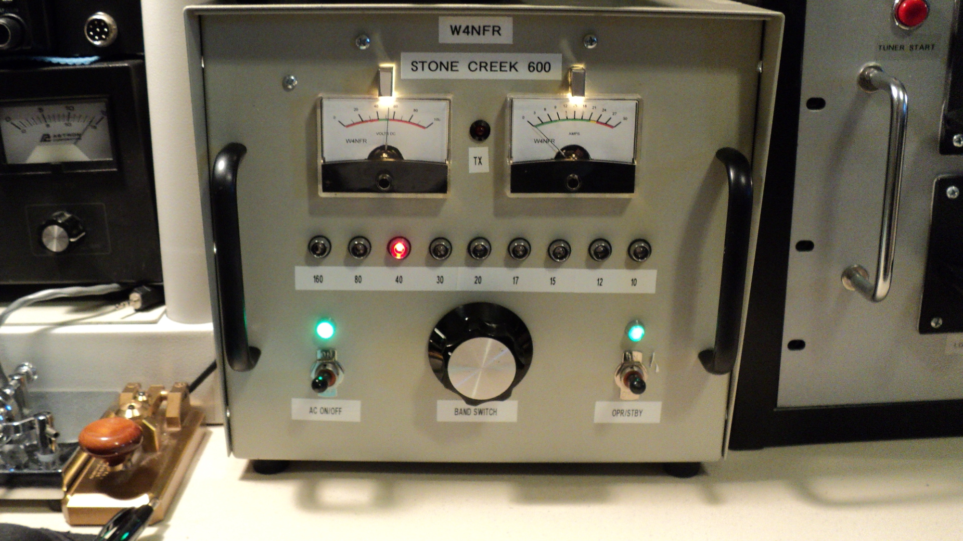
NEW FRONT VIEW
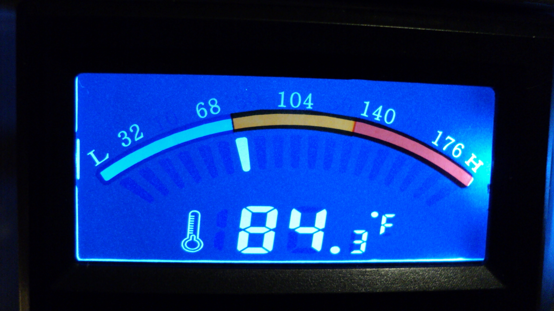
This Temperature Meter Was Added To Measure The Heat Spreader Temp
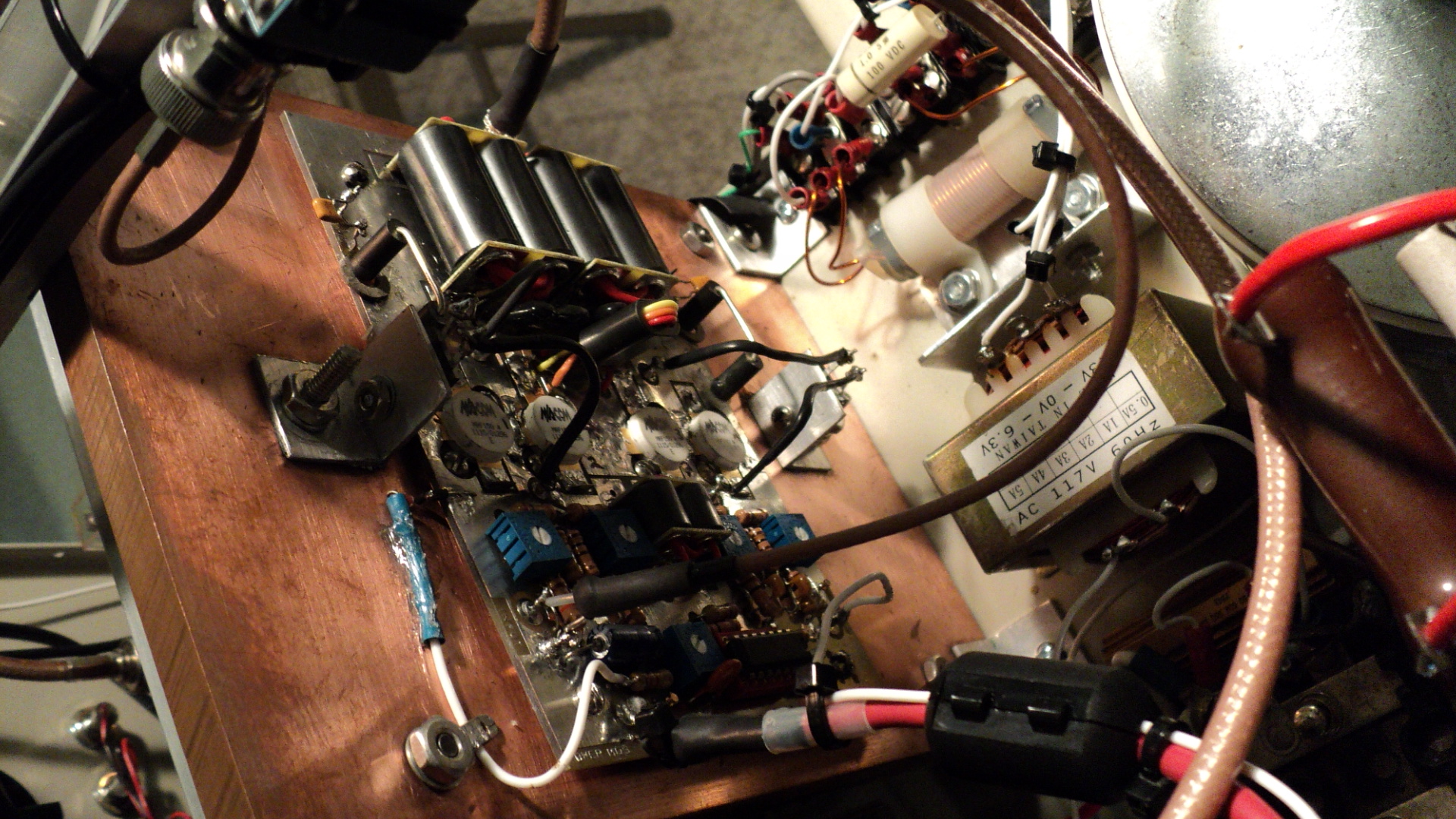
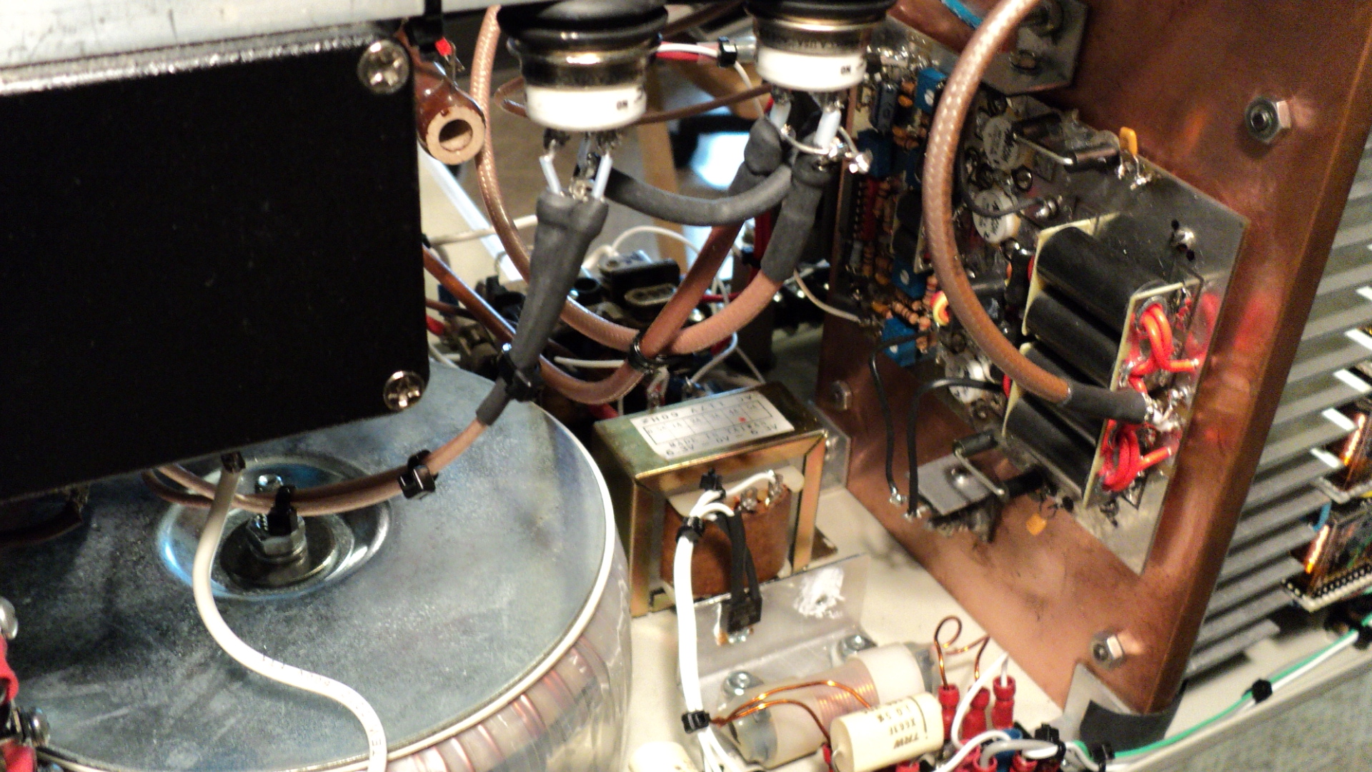
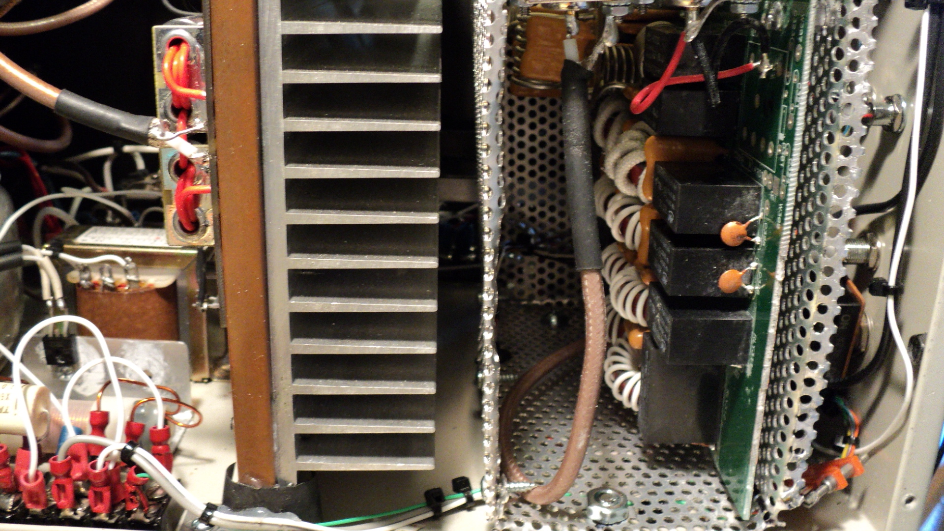
AMPLIFIER BOARD ON COPPER HEAT SPREADER
FeedBack Resistors on HS Either Side of Board
Temperature Sensor on Copper Spreader
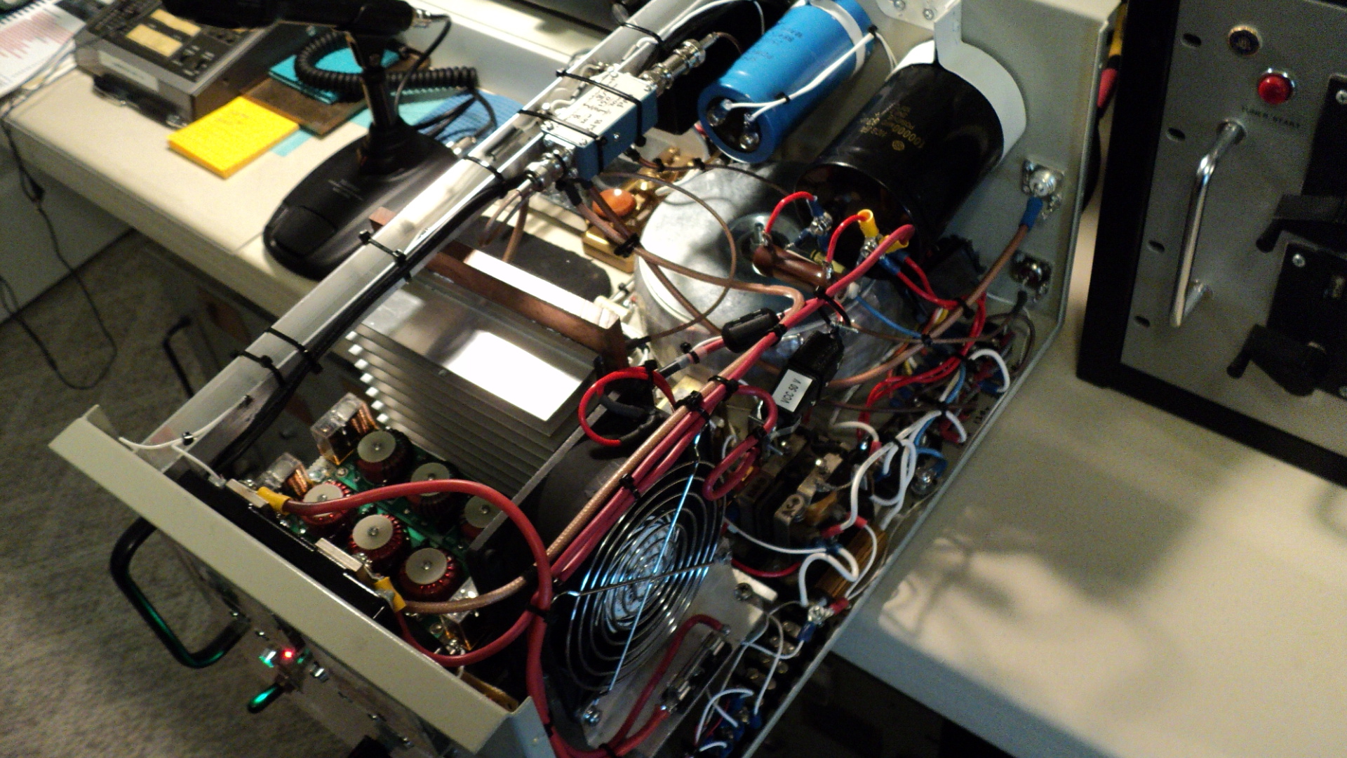
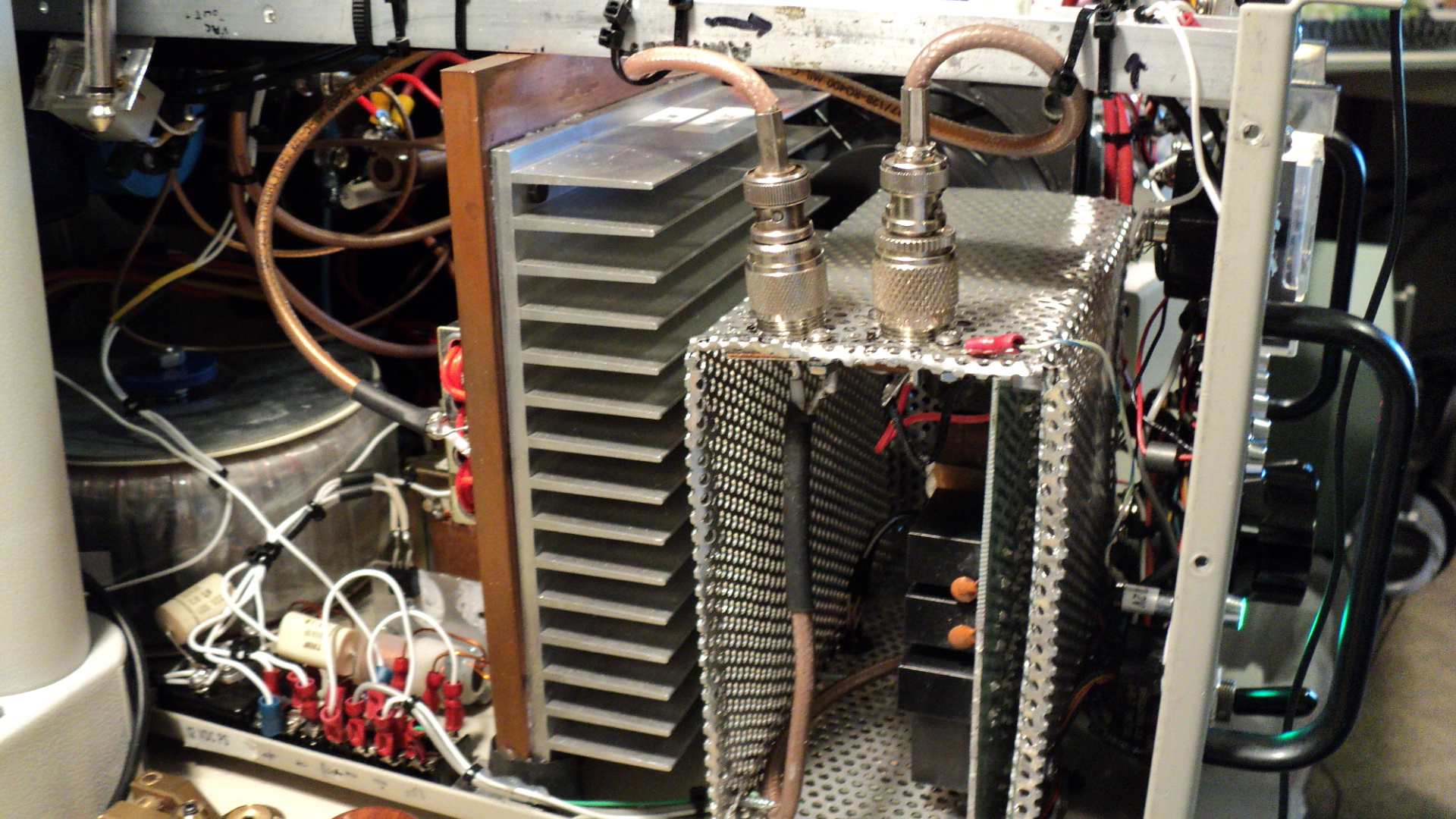
TOP RIGHT VIEW OF PS, 12 vdc COOLING FAN, FILTER, HEAT SINK AND POWER TOROID
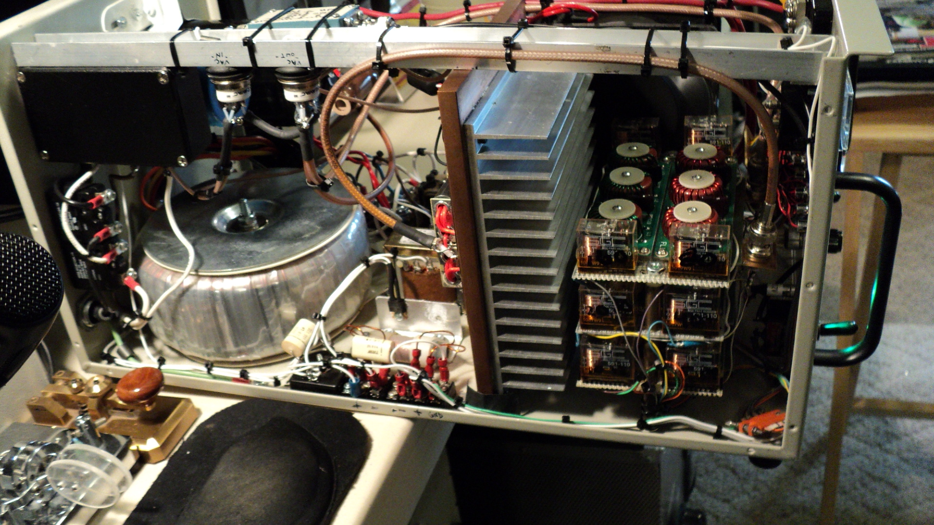
SIDE VIEW SHOWING POWER TOROID, LV 12 VDC POWER SUPPLY,
HEAT SINK AND (OLD) CCI HARMONIC FILTER BANK
The Vacuum RF Relays are now in a shield box.
POWER AMPLIFIER, KILOVAC RELAYS were later moved to a shielded box.
Original Front View
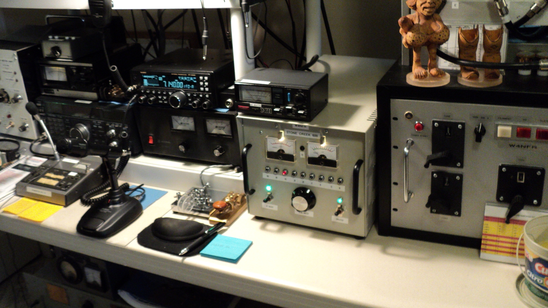
Amplifier In Use With The Yaesu FT-450D, 12 Watts In (Thru a 3 DB Pad) then in
and 600 Watts Out

SCHEMATIC DIAGRAM FROM EB104 BULLETIN
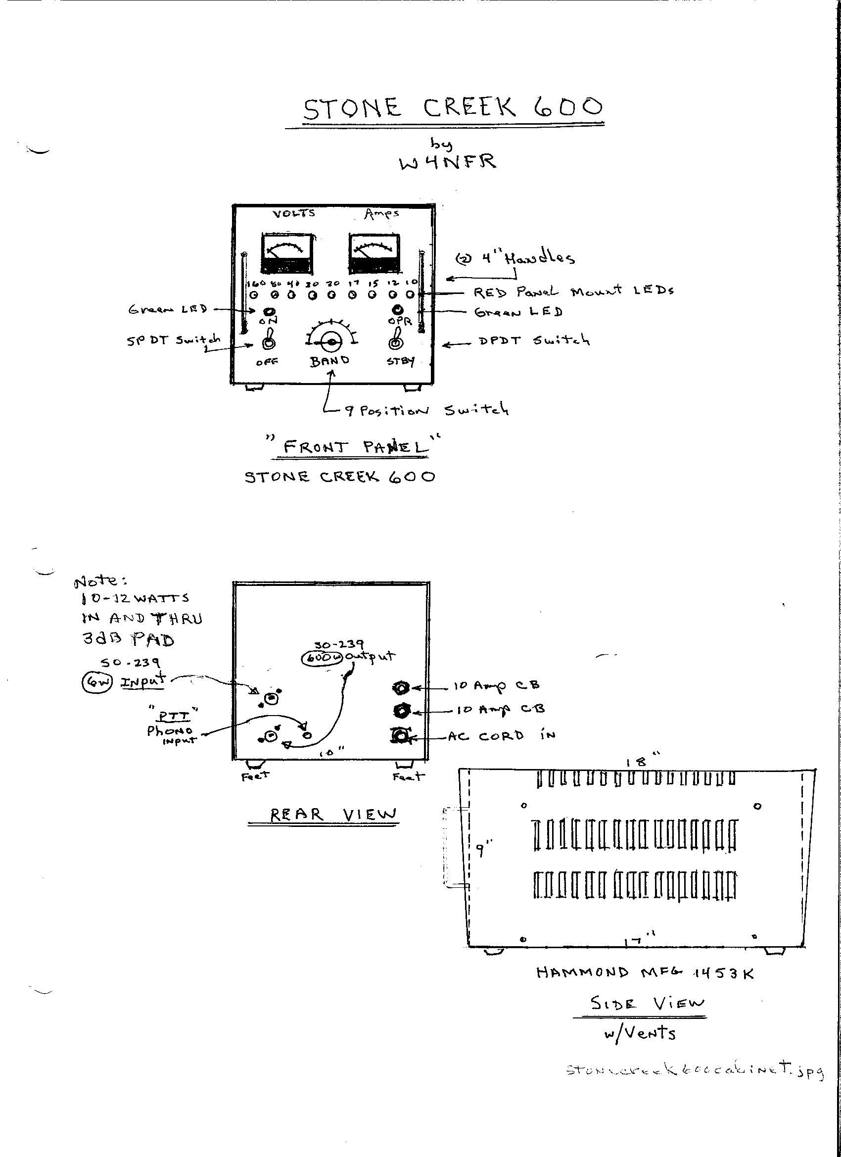
AMPLIFIER CABINET
\
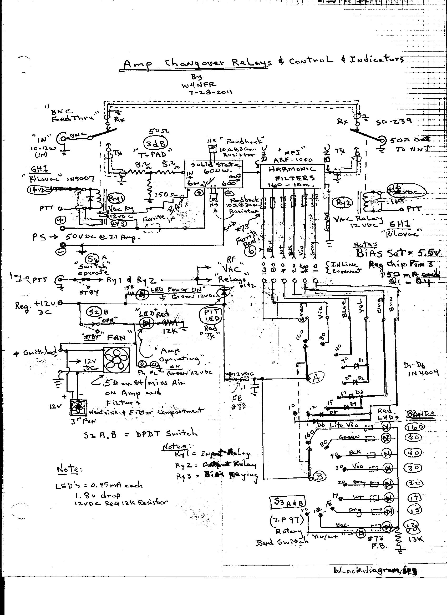
BLOCK DIAGRAM

POWER SUPPLY

MFJ AMERITRON MODEL ARF-1000
HARMONIC FILTERS
There is no schematic of the MFJ Filter Included In the Package, but it is the same as ALS-600 Amplifier Harmonic Filter.
Refer to the ALS-600 Parts List for Component Values and the Drawing.
NEW LP FILTER BOARD IN THE CAGE
NEW MFJ ARF-1000 HARMONIC FILTER PROVIDES AN ADDITIONAL 100 WATTS OUTPUT
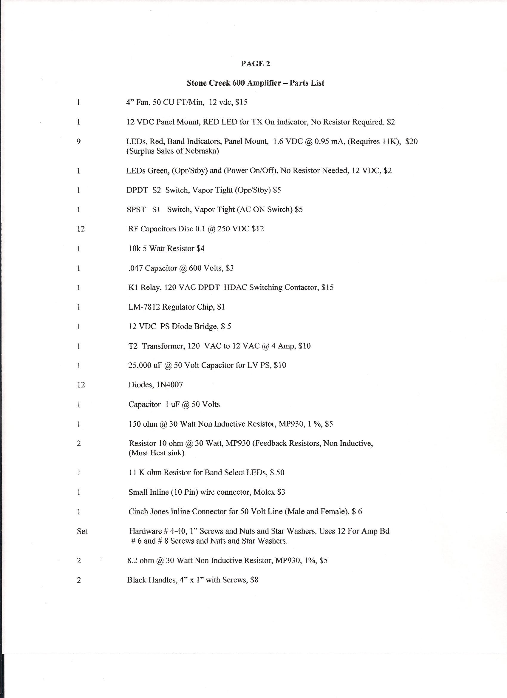
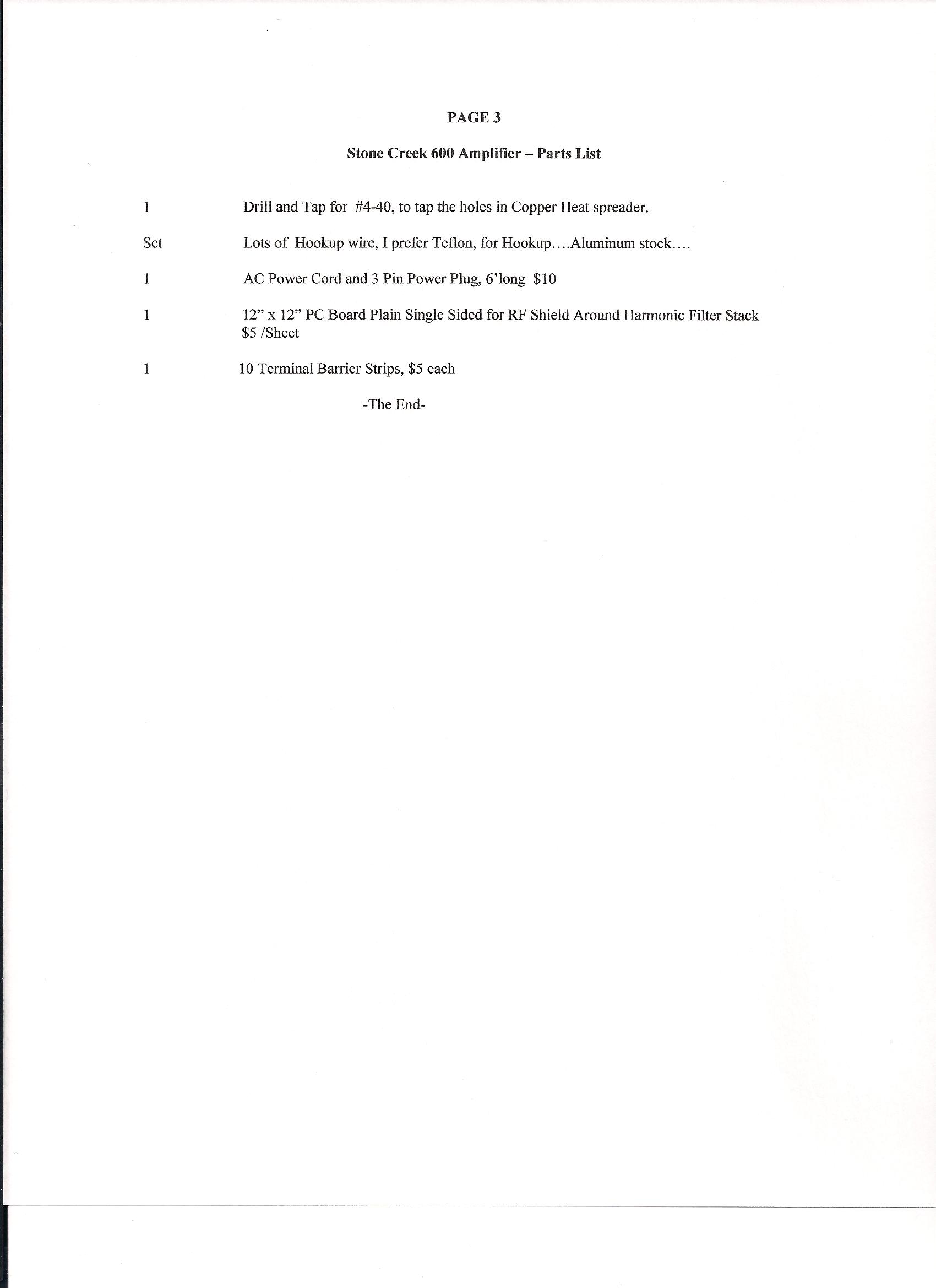
Parts List
-FYI-
Notes and Comments
I would say you can use the 40 volt @ 60 amp supply. The output will be reduced some, but will work.
I use the 50 volt supply to feed the bias pin. The regulator on the board works very well. I set my R5
bias pot for 5.5 vdc at IC-1 pin 3. Make sure you put a 2 amp meter and fuse in line with your Vcc power supply feeding
your Vds input. Make sure the individual bias pots are Minimum. Put a 50 ohm load on the output of amp, even
though you are not putting RF to it yet. Set R1 very slowly for idle current of 150 mA, R2 for a reading
of 300 mA,R3 for 450 mA and finally R4 for 600 mA on the 2 amp meter. I have found this to be a very stable operating range.
I changed the R1-R4 Bias pots to 10K 20 turn pots to adjust more precisely.
The MFJ ARF-1000 Low Pass filter is very good.
I found that the 12vdc input jack on the MFJ ARF-1000 is kinda flakey, so I did away with it. I have a 12 vdc
supply in the amp to provide power for my LEDs and relays, so I powered the ARF-1000 with it too. I removed the built-in
MFJ switch and used my own, but you can use it for your application. I just happened to have my own switch built-in.
I put my filter board inside a shielded cage to isolate it from the amp, but I am not sure you really have to do that. MFJ
does not in their MFJ AL-600. I now key my bias on Tx when I key the RF change over relays.
I use vacuum relays, but not necessary. A good RF open frame relay will work. If you want high speed switching, use vacuum.
The important thing is to have a good 50 ohm load on the output/or an antenna that is resonant on the band you are using.
The amp will take a 2:1 VSWR, but I don't know how long. I like to make sure the antenna SWR is flat.
I measure my RF out using a Peak Reading WM and I use a "Pecker Pulser" to excite my Transceiver.
This does not over stress the amp and gives me a good indication of the output.
Also, make sure the Ferrite's on L1 and L2 are well insulated from ground. They will catch fire if they touch ground.
If you have a bad load on the Amp output, C13 and C14 can burn up too. Don't ask how I know this!
Well good luck on your project. You can set the bias and get that done without the ARF-1000. Setting the bias will
pretty much tell you if the PA MosFets are working. The pots are very touchy, so adjust very slowly and carefully if
you use the stock one turn pots. I put a dab of RTV on them when finished. The bias adjustment will insure
a good stable operation. You don't want a run away oscillation amp.
When you get done, make sure you have a fan to cool the heat-sink. I use a low noise
50 cfm 4" muffin and a 3" muffin an that runs on 12 vdc. Very quiet and moves the air well.
I started with a 120 vac fan that moves 100 cfm but it was too noisy. The 12 vdc fans works very well.
When you drive the amp, I use a little 3 dB pad on the input and drive with 12 watts.
With no pad on the input, use no more than 6 watts. Let me know how the project works out for you.
Another ham here in my area just built one of these and he was disappointed with output.
I checked it out here and it worked as good as mine.
His problem was low AC line voltage at his house. He ran a separate ac line to his shack to power the amp
and it works much better now. So line voltage is important. You may see some reduced output with a 40 volt supply.
My supply drops from 52 volts dc to 40 vdc when keyed and modulated with SSB, so maybe you will be ok with the stiff 40 vdc at 60 amps supply.
I added a small LCD Temperature Meter to the right upper front corner and mounted the temp probe to the Copper Spreader to measure
the heat created by the MosFet devices. This will alert me if the fans can not handle the heat.
Hope you enjoyed my amplifier building adventure !
73's
Bill W4NFR
************THE END************